Double-flapping-wing generating set

A technology for power generation devices and generators, which is applied in wind power generation, ocean power generation, engines, etc., can solve the problems of limiting blade amplitude, efficiency and power are not ideal, and cannot play the role of multi-wing mutual promotion, so as to improve adaptability , Improve the effective camber and lift, improve energy absorption efficiency and power

Active Publication Date: 2016-08-31
XI AN JIAOTONG UNIV
View PDF7 Cites 19 Cited by
  • Summary
  • Abstract
  • Description
  • Claims
  • Application Information

AI Technical Summary

Problems solved by technology

[0003] The existing flapping wing energy-absorbing mechanism often has only one blade, and uses a mechanism such as a crank connecting rod to convert linear motion into rotary motion. This flapping wing design cannot take advantage of the mutual promotion of multiple wings, and the efficiency and power are not equal. Not optimal, and the crank connecting rod severely limits the amplitude of the blades, resulting in less adaptability of the flapping wing generator to different incoming flows

Method used


Image

  • Double-flapping-wing generating set
  • Double-flapping-wing generating set
  • Double-flapping-wing generating set

Examples


Embodiment Construction

[0025] The present invention will be further described in detail below in conjunction with the accompanying drawings.

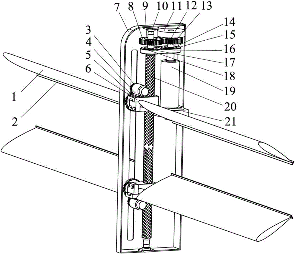
[0026] The overall schematic diagram of the double flapping wing power generation device provided by the present invention is as follows: figure 1 , the technical scheme adopted is as follows:

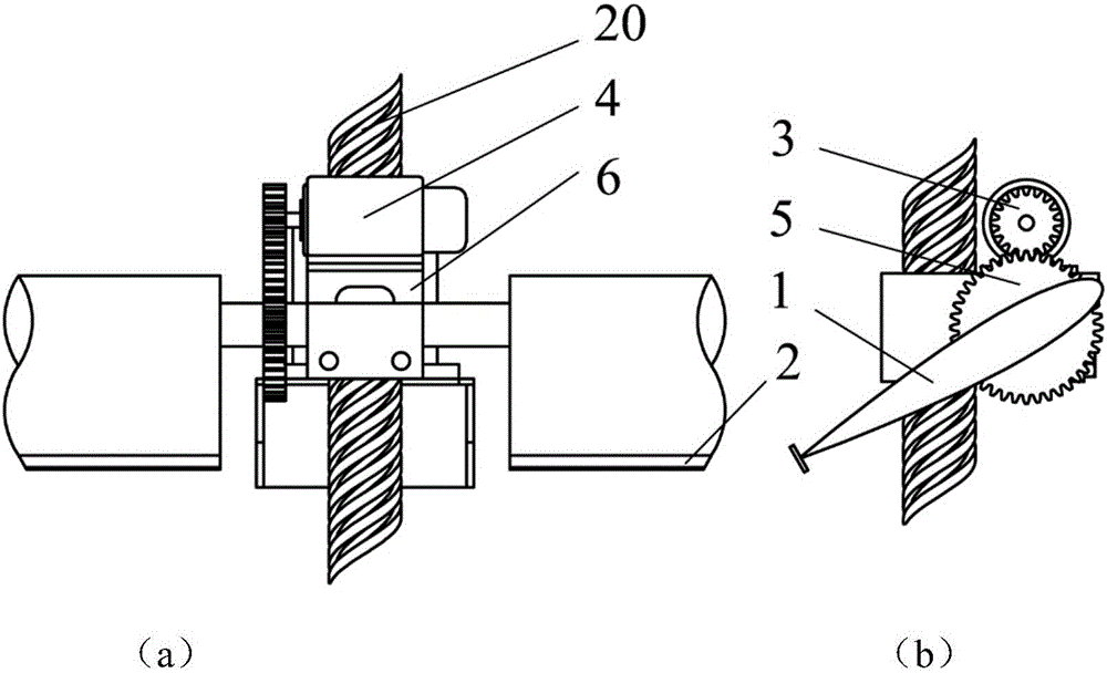
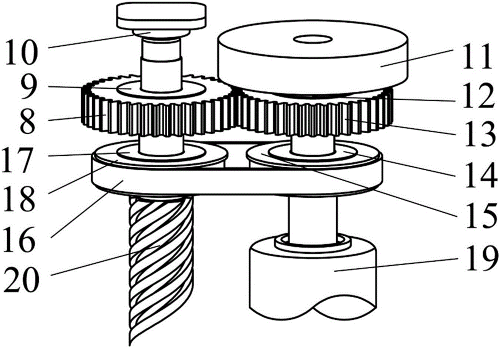
[0027] Every two blades 1 form a group with the same axis. There are two groups of blades arranged symmetrically side by side as shown in the figure. Flaps 2 are arranged at the trailing edge of blades 1 to improve energy absorption efficiency. A second gear 5 is fixed on it. The rotating shaft of the blade 1 can rotate on the first platform 6 , and the first platform 6 can slide along the screw rod 20 . Such as figure 2 As shown, a servo motor 4 is also fixed on the first platform 6 , and the servo motor 4 drives the pitching motion of the blade 1 through the first gear 3 and the second gear 5 meshing with each other. When the blade 1 pushes the first platform 6...


PUM


Abstract

The invention discloses a double-flapping-wing generating set. The double-flapping-wing generating set comprises a shell and a lead screw. The lead screw is parallel to the shell, and the two ends of the lead screw are movably connected with the shell. The upper part and the lower part of the lead screw are each movably connected with a transmission mechanism. Each transmission mechanism can slide vertically when the lead screw rotates. Each transmission mechanism is provided with a set of blades. The two blades in each set are coaxially arranged in the direction perpendicular to the axis of the lead screw and connected through a rotating shaft. The transmission mechanisms can drive the corresponding rotating shafts to rotate. In addition, a generating set body for generating power through rotation of the lead screw is arranged on any side of the shell. According to the generating set for collecting fluid kinetic energy through double-flapping-wing pitching-heaving motion, the two sets of blades in the generating set are symmetrically arranged side by side, the pitching motion phase difference between the two sets of blades is 180 degrees, the two sets of blades can be the end walls of each other by means of the arrangement, and the energy absorption efficiency and power of the generating set can be improved through the end wall effect.

Description

Technical field: [0001] The present invention relates to a power generation device, in particular to a wind power or hydropower power generation device, in particular to a double flapping wing power generation device. Background technique: [0002] With population growth, economic development and social progress, people's demand for energy, especially clean energy, is increasing. The power generation of traditional hydropower stations and wind turbines has been increasing year by year, but their impact on the environment has also attracted increasing attention. For example, the impact of hydropower stations on upstream and downstream ecology and local landforms, the noise pollution of large wind turbines and their impact on migratory bird migration. The installed capacity of traditional hydropower stations and wind turbines, especially hydropower stations, is gradually approaching their limit values. In this context, conventional water turbines and wind turbines as well as...

Claims


Application Information

Patent Timeline
Patent Type & Authority Applications(China)
IPC IPC(8): F03B17/06F03D5/06F03D9/25F03D15/10
CPCF03B17/06F03D5/06F05B2260/40F05B2220/706Y02E10/70Y02E10/30
Inventor 谢永慧姜伟张荻
Owner XI AN JIAOTONG UNIV
Why Eureka
Try Eureka