On-site calibration device for phased array antenna

A phased array antenna, field calibration technology, applied in radio wave measurement systems, instruments, etc., can solve the problems of difficult use, large receiving antenna size, inability to meet the requirements of transmitting antenna units, etc., to achieve convenient installation, guarantee authenticity, The effect of ensuring accuracy

Active Publication Date: 2016-08-31
CHINA ELECTRONIC TECH GRP CORP NO 38 RES INST
View PDF6 Cites 18 Cited by
  • Summary
  • Abstract
  • Description
  • Claims
  • Application Information

AI Technical Summary

Problems solved by technology

This method is limited by the requirements of the test site, and it is easily affected by environmental scattering and multipath effects during the test process, which often has large errors and is difficult to use in the actual environment; the usual near-field calibration uses open waveguide, coupler Pole antennas and horn antennas are used as receiving antennas, but when measuring the radiation field of phased array radar antenna units, these receiving antennas are large in size, which can neither meet the one-to-one correspondence with the transmitting antenna units, nor solve the problem of adjacent antenna units. coupled field problem
Both patent CN 102472785 and patent CN 103105541B disclose a method and device for near-field measurement of electromagnetic fields. The near-field probe measures the light intensity change caused by the change of the electromagnetic fie

Method used


Image

  • On-site calibration device for phased array antenna
  • On-site calibration device for phased array antenna

Examples


Embodiment Construction

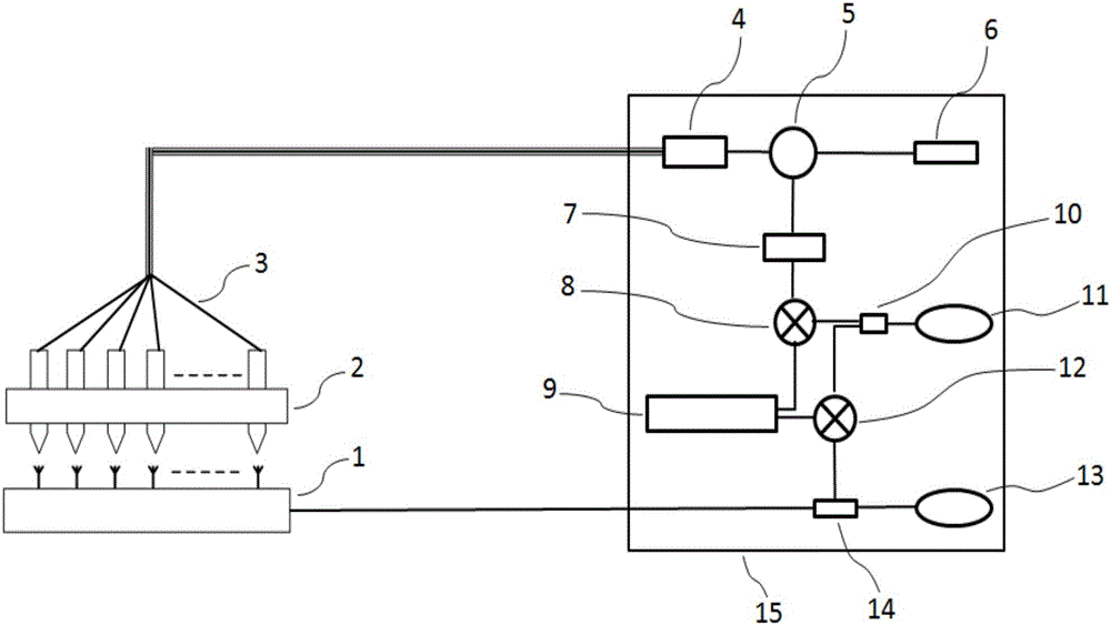
[0015] Such as figure 1 As shown, a device for on-site calibration of a phased array antenna includes an optical probe array 2 and a signal processing system 15; Each optical probe in the probe array 2 corresponds to an antenna unit, and the distance between each probe and the antenna unit and its consistency are precisely controlled, and the optical probe array is connected to the signal processing system 15 through a polarization-maintaining optical fiber 3 .

[0016] In order to prevent the too strong electromagnetic interference signal from the antenna array from entering the signal processing system and affecting the normal operation of other internal electronic devices, the system uses a long polarization-maintaining optical fiber to connect the optical probe array and the signal processing system, so that the signal processing The system is far away from the radar emission front, reducing the accuracy of radar signal interference measurement. At the same time, in order...


PUM


Abstract

The invention belongs to the field of microwave near field measurement and specifically relates to an on-site calibration device for a phased array antenna. The on-site calibration device comprises an optical probe array and a signal processing system, wherein the optical probe array is erected on a phased array antenna array face via a fixed machine rack, each optical probe in the array corresponds to an antenna unit and is used for precisely controlling distance and consistency between each optical probe and the antenna unit, the optical probe array is connected with the signal processing system via polarization maintaining optical fibers, and excitation of the antenna array face is provided by a excitation signal source in the signal processing system via a straight-through end of a directional coupler. The optical probe array does not contain any metal device, no near field radiation field of a radar antenna can be affected, measurement realness can be ensured, probes are positioned very near to the antenna units, the device cannot be affected by multipath effects produced by electromagnetic fields reflected by the ground or objects or the like and interference such as coupling effects and the like between antenna units, and measurement accuracy can be ensured.

Description

technical field [0001] The invention belongs to the field of microwave near-field measurement, and in particular relates to a device for on-site calibration of a phased array antenna. Background technique [0002] Phased array radar is named for its phased array antenna. It is used in military fields such as homeland air defense, missile defense system, shipboard, airborne and spaceborne fire control, early warning system, and even in radio astronomy, satellite communication, meteorological and hydrological The wide application of various sectors of the national economy such as air traffic control, earth exploration and biomedicine has attracted more and more attention and attention from the world. Phased array antennas are generally large in size, and many of them have tolerances in the manufacture and assembly of components, as well as the influence of mutual coupling between antenna elements, often causing considerable amplitude and phase errors in each channel, which cau...

Claims


Application Information

Patent Timeline
IPC IPC(8): G01S7/40
CPCG01S7/4004
Inventor 张业斌田晓光王昌雷武帅张思敏盛永鑫
Owner CHINA ELECTRONIC TECH GRP CORP NO 38 RES INST
Why Eureka
Try Eureka