Powered parafoil system's air-drop wind field identification method

A technology of powered parafoil and identification method, which is applied in the direction of control/regulation system, non-electric variable control, instrument, etc., and can solve problems such as deviation of measurement results and poor measurement accuracy

Inactive Publication Date: 2016-08-31
NANKAI UNIV
View PDF3 Cites 10 Cited by
  • Summary
  • Abstract
  • Description
  • Claims
  • Application Information

AI Technical Summary

Problems solved by technology

However, the load of the parafoil system and the parafoil itself are a kind of flexible connection, with relative motion, the yaw angle measured by the gyroscope has a certain deviation from the flight direction of the parafoil system, so the measurement results have a large deviation, and the measurement accuracy poor

Method used


Image

  • Powered parafoil system's air-drop wind field identification method
  • Powered parafoil system's air-drop wind field identification method
  • Powered parafoil system's air-drop wind field identification method

Examples


Embodiment 1

[0081] Embodiment 1: Single downward bias control (simulation 1)

[0082] (1) Wind field identification of powered parafoil system under stable wind field

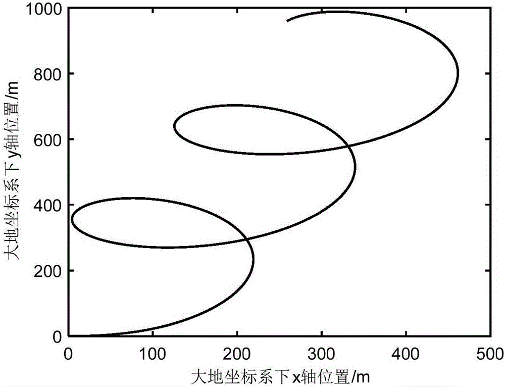
[0083] The single downward deflection control of the powered parafoil system is in a circular motion in a windless state, and the radius of the circle is related to the downward deflection. When the influence of the wind field is added, the trajectory of the powered parafoil will shift along the direction of the wind field under the action of the wind field.

[0084] image 3 displayed on V W When =(12)m / s wind field, the horizontal trajectory of the powered parafoil system under the control action of single downward deviation of 40%. The parameters of the powered parafoil system are shown in Table 1.

[0085] Table 1 Power parafoil system parameters

[0086]

[0087] From image 3 and Figure 4 It can be seen that the powered parafoil system spirals forward along the wind direction, and its ground speed varies p...

Embodiment 2

[0116] Embodiment 2: Wind field identification during trajectory tracking control (simulation 2)

[0117] The wind field identification accuracy of the parafoil system is ideal in the single downward deflection state, but in some cases the movement area of ​​the parafoil system is limited, and it is not allowed to fly with the wind in the single downward deflection state. Wind field identification in control state.

[0118] The previous chapters introduced the control method for the parafoil system to track the reference trajectory. The parafoil system can track the circular trajectory under the control of the linear active disturbance rejection controller. By controlling the parafoil system to track the circular trajectory, the movement of the parafoil system The area is limited within a certain range. Figure 10 is parafoil system V W =(1 2)m / s In the wind field, the track of the horizontal projection is tracked when the altitude-fixed circular track is collected to collec...

Embodiment 3

[0123] Embodiment 3: Wind field identification (simulation 3) of powered parafoil system landing stage

[0124] The powered parafoil system can accurately identify the wind speed and direction of the wind field where it is located by means of single downward deflection or tracking the circular trajectory. The wind field information plays an important role in the homing control, trajectory tracking and sparrow landing operation of the powered parafoil. . In this embodiment, the landing control of the powered parafoil system is taken as an example. Firstly, the wind field is identified by using the powered parafoil to track a circular trajectory, and then the headwind alignment and landing are performed.

[0125] Figure 12 and Figure 13 Indicates the horizontal trajectory and wind field identification results of the landing process. The stable wind field vector added to the system is V w = (0 3) m / s.


PUM


Abstract

The invention provides a powered parafoil system's air-drop wind field identification method which can dynamically identify the wind speed and wind direction of a wind field that a powered parafoil system flies across so as to provide necessary information for reference to control the trajectory of the parafoil system and the operations for flared landing. The identification process for a wind field is divided into three steps. Firstly, through a GPS module, the positions concerned information of the powered parfoil system can be obtained. Based on the change in the positions of the powered parafoil system, the flying speed and the direction of the powered parafoil system can be calculated. Secondly, the Kalman filtering algorithm is adopted to have the flying speed of the powered parafoil system undergo a filtering process so as to get accurate speed concerned information. Thirdly, the recursive least square algorithm is introduced to online update the identification results of the wind field.

Description

technical field [0001] The invention belongs to the field of unmanned aircraft control, and relates to a method for identifying wind field information of the flight environment of a powered parafoil system. Background technique [0002] The parafoil is a special parachute evolved from the traditional round parachute. It has a history of more than 50 years since its creation. The parafoil is characterized by controllability, gliding, safety and large load ratio. It can realize the turning action by manipulating the parachute and control the flight direction of the parafoil. With the development of science and technology and the transformation of military strategic thinking, precise airdrop and "fixed-point non-destructive" landing are more and more widely used in military, aerospace and other fields. In modern warfare, ground combat troops can replenish weapons, ammunition, and supplies in a timely manner through airdrops, which is convenient and efficient; in the event of m...

Claims


Application Information

Patent Timeline
Patent Type & Authority Applications(China)
IPC IPC(8): G05D1/10
CPCG05D1/105
Inventor 孙青林檀盼龙赵宏高海涛陶金陈增强蒋玉新
Owner NANKAI UNIV
Why Eureka
Try Eureka