High-torque-density permanent magnet reluctance synchronous motor rotor structure

A reluctance synchronous, motor rotor technology, applied in the direction of magnetic circuit shape/style/structure, magnetic circuit, electrical components, etc., can solve the problem of insufficient utilization of torque components, etc., to improve utilization rate, increase torque density, The effect of reducing consumption

Active Publication Date: 2016-08-31
江苏仪能电机有限公司 +1
View PDF8 Cites 36 Cited by
  • Summary
  • Abstract
  • Description
  • Claims
  • Application Information

AI Technical Summary

Problems solved by technology

[0005] Purpose of the invention: In order to overcome the shortcomings of insufficient utilization of the two torque components in the prior art, the present invention provides a high torque density permanent magnet reluctance synchronous motor rotor structure, which can more fully utilize the permanent magnet torque component and reluctance torque components, thereby increasing the torque density of the motor

Method used


Image

  • High-torque-density permanent magnet reluctance synchronous motor rotor structure
  • High-torque-density permanent magnet reluctance synchronous motor rotor structure
  • High-torque-density permanent magnet reluctance synchronous motor rotor structure

Examples


Embodiment Construction

[0021] The present invention will be further described below in conjunction with the accompanying drawings.

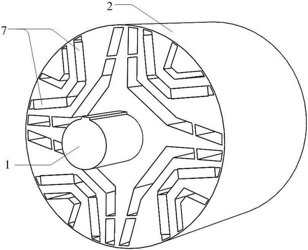
[0022] Such as figure 1 Shown is a high torque density permanent magnet reluctance synchronous motor rotor structure, including a central shaft 1 and a rotor core 2 (made of laminated rotor punches), the central shaft 1 and rotor core 2 are installed on the same central axis ;Around the central axis, P slot groups 3 with the same structural size are evenly arranged on the rotor core 2, and along the clockwise direction, the numbers of the slot groups 3 are sequentially recorded as 1, 2, . . . , i, . ··, P-1, P, where P is the number of magnetic poles of the motor;

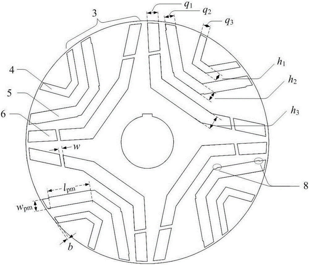
[0023] Such as figure 2 As shown, each slot group 3 includes three U-shaped slots, each U-shaped slot includes a straight base and two straight flanks, and the three straight bases are parallel to each other; according to the distance between the straight base and the central axis distance, the three ...


PUM


Abstract

The invention discloses a high-torque-density permanent magnet reluctance synchronous motor rotor structure, which comprises a central rotating shaft and a rotor core, wherein P groups of through slots are evenly formed in the rotor core along the circumferential direction, each group of through slots includes three layers of U-shaped through slots formed along a radial direction of the rotor core at intervals, and a permanent magnet is embedded in each of two wings of the middle U-shaped through slot; and the middle U-shaped through slot among the three layers of U-shaped through slots is of a symmetric structure, and the outer-layer and inner-layer U-shaped through slots are each of asymmetric structure. The high-torque-density permanent magnet reluctance synchronous motor rotor structure can change torque characteristics of a built-in permanent magnet synchronous motor, makes the maximum synthesized torque fully utilize a permanent-magnet torque component and a reluctance torque component, and increases torque density of a motor.

Description

technical field [0001] The invention relates to a high torque density permanent magnet reluctance synchronous motor rotor structure, which belongs to the permanent magnet motor technology. Background technique [0002] There are permanent magnets distributed in the permanent magnet synchronous motor rotor according to certain rules, and the magnetic flux provided by the permanent magnets replaces the excitation of the excitation winding of the electric excitation synchronous motor to establish the main magnetic field. According to the structure of the rotor magnetic circuit, it can be divided into surface type and built-in type. The permanent magnet of the built-in rotor magnetic circuit structure is located inside the rotor core, and its rotor magnetic circuit structure is a salient pole structure. In addition to the permanent magnet torque component, there is also a reluctance torque component in the electromagnetic torque. [0003] According to the torque characteristics...

Claims


Application Information

Patent Timeline
Patent Type & Authority Applications(China)
IPC IPC(8): H02K1/27
CPCH02K1/27H02K2201/06H02K2213/03
Inventor 邹兆林陈可来邹其辉柳阳孔永林明耀
Owner 江苏仪能电机有限公司
Why Eureka
Try Eureka