

Charge bleed-off method, bleeder circuit and converter
A bleeder circuit and inverter technology, applied in the field of inverters, can solve problems such as hidden safety hazards, energy waste, energy consumption and the like
- Summary
- Abstract
- Description
- Claims
- Application Information
AI Technical Summary
Problems solved by technology
Method used
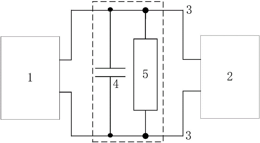
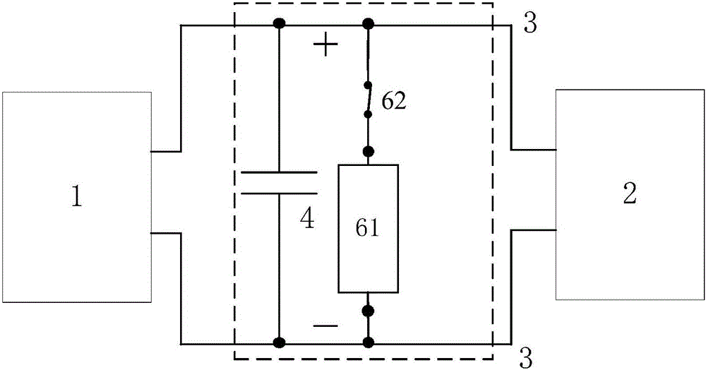
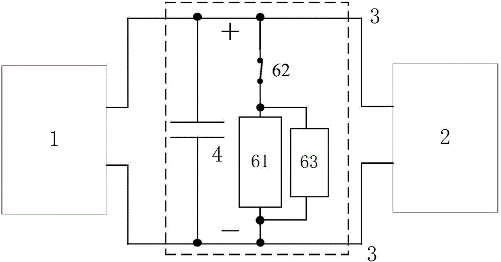
Image

Examples
no. 1 Embodiment
[0060] In the first specific embodiment of the present invention, the contactor may specifically be a DC contactor. The bleeder circuit may also include a controller where:
[0061] The DC contactor coil is connected with the controller, and the DC contactor coil is powered by the controller.
[0062] When the inverter system is powered on, the controller is powered on first, and then the coil of the DC contactor is powered on through the switch output, so that the normally closed contact of the DC contactor is disconnected, and the discharge circuit is cut off.
[0063] When the converter system is powered off, the controller is powered off and stops working, and the coil of the DC contactor is powered off, so that the normally closed contacts of the contactor are closed, and the discharge circuit is connected to discharge the residual charge of the DC bus.
no. 2 Embodiment
[0065] In the second specific embodiment of the present invention, the contactor may specifically be an AC contactor, and the coil of the contactor is powered by alternating current.
[0066] The power-on and power-off sequence of the AC contactor coil is consistent with the power-on and power-off sequence of the converter.
[0067] The AC contactor coil and the inverter system can be powered by the same AC power source.
[0068] When the converter system is powered on, the coil of the DC contactor is energized, so that the normally closed contacts of the DC contactor are disconnected, and the residual charge discharge circuit of the DC bus is disconnected.
[0069] When the converter system is powered off, the coil of the DC contactor is powered off, so that the normally closed contact of the DC contactor is closed, connected to the DC bus residual charge discharge circuit, and the DC bus residual charge is discharged.
[0070] In the first specific embodiment of the present...
PUM
 Abstract
Description
Claims
Application Information