Cooling fin and cooling fin type crystallizing tank and cooling method thereof

A technology for cooling fins and crystallizing tanks, which is applied in the directions of heat exchange cooling crystallization, solution crystallization, crystallizing adjustment/control, etc. It can solve the problem of large temperature difference between the cooling medium and the material to be crystallized, the difficulty of realizing the production of large-capacity crystallizing tanks, and the difficulty of equipment manufacturing. Increase and other problems to achieve good heat transfer effect, guaranteed strength, and low resistance

Inactive Publication Date: 2016-09-07
立钢贝纳德工程设备(广州)有限公司
View PDF6 Cites 1 Cited by
  • Summary
  • Abstract
  • Description
  • Claims
  • Application Information

AI Technical Summary

Problems solved by technology

[0004] Disadvantages of the coil crystallization tank: (1) It is difficult to process and manufacture, and the installation needs to support the steel along the direction of the cylinder; (2) The volume-to-area ratio is relatively small, and the temperature difference between the cooling medium and the material to be crystallized is large, and the crystallization of the same material will increase the refrigerator. (3) When the height of the cylinder is high, in order to avoid the large temperature difference between the inlet and outlet of the cooling medium, it is necessary to set the inlet and outlet in sections in the direction of th

Method used


Image

  • Cooling fin and cooling fin type crystallizing tank and cooling method thereof
  • Cooling fin and cooling fin type crystallizing tank and cooling method thereof
  • Cooling fin and cooling fin type crystallizing tank and cooling method thereof

Examples


Embodiment Construction

[0036] The present invention will be described in further detail below.

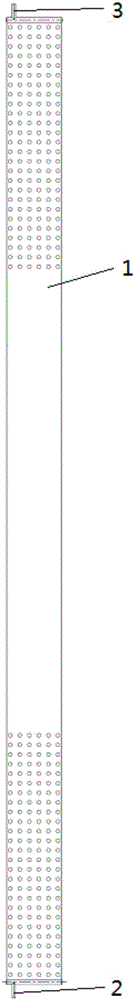
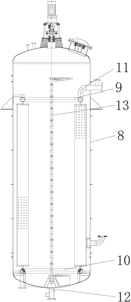
[0037] A cooling fin type crystallization tank includes: a tank body, an upper coil, a lower coil, an upper inlet and outlet pipe, a lower inlet and outlet pipe, a stirring paddle, and a plurality of cooling fins.

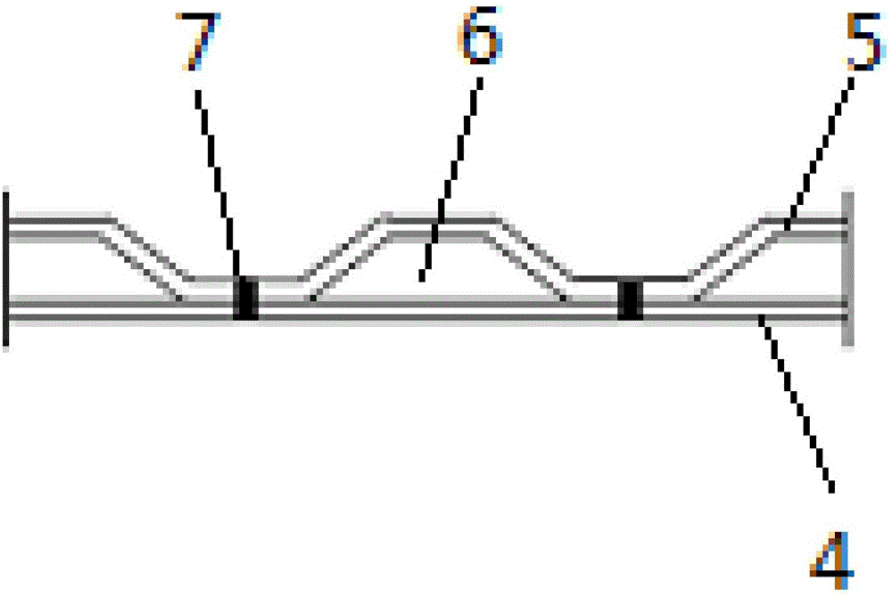
[0038] The cooling fin includes a fin body, an inlet of cooling medium, and an outlet of cooling medium. The fin body is in the shape of a rectangular hollow thin plate, one side is a flat plate, and the other side is a profiled plate. The end face of the shell pressed into the shape of the profiled plate is a concave-convex surface. The flat plate and the profiled plate are contacted through the concave-convex surface. Laser welding or butt welding is used. The surroundings of the fin body are sealed by full welding to form a closed cavity as a cooling medium. circulation channel. The number of shape shells is multiple, evenly distributed where the intensity is low. The cross section of t...


PUM


Abstract

The invention relates to a cooling fin. The cooling fin comprises a fin body; a cavity containing a cooling medium is formed in the fin body, a cooling medium inlet is formed in one end of the fin body, and a cooling medium outlet is formed in the other end of the fin body. The invention further relates to a cooling fin type crystallizing tank with multiple cooling fins. The cooling fin type crystallizing tank comprises a tank body, an upper coil pipe and a lower coil pipe; the upper coil pipe is located on the upper portion inside the tank body and communicated with the cooling fins, and the lower coil pipe is located on the lower portion inside the tank body and communicated with the cooling fins; the upper coil pipe is connected with an upper in-out pipe penetrating out of the tank body, and the lower coil pipe is connected with a lower in-out pipe penetrating out of the tank body. The invention further relates to a cooling method of the cooling fin type crystallizing tank. The cooling fin and the cooling fin type crystallizing tank and the cooling method thereof have the advantages that the large-capacity area ratio is easy to configure, the temperature difference between the cooling medium and a crystallized material is decreased, and energy saving is relatively achieved and belong to the technical field of crystallizing tank cooling.

Description

technical field [0001] The invention relates to a cooling technology for a crystallization tank, in particular to a cooling fin, a crystallization tank equipped with the cooling fin, and a cooling method for the crystallization tank. Background technique [0002] At present, there are two main cooling methods commonly used in crystallization tanks used for cryogenic crystallization fractionation or dewaxing: one is the coil type, and the other is the curved surface cooling plate type concentric with the shell. [0003] The structure of the coiled crystallization tank is as follows: a steel bracket parallel to the cylinder is installed inside the crystallization tank, and spiral coils with equal or unequal pitches are fixed on the inside and outside of the bracket along the diameter of the cylinder, in order to overcome the impact of the steel on crystallization. The dead zone formed by the obstruction of the flow channel of the tank needs to open holes in the section steel t...

Claims


Application Information

Patent Timeline
IPC IPC(8): B01D9/02
CPCB01D9/0013B01D9/0063
Inventor 程玉龙
Owner 立钢贝纳德工程设备(广州)有限公司
Why Eureka
Try Eureka