Magnetic core chamfering machine applied to annular magnetic core

A ring magnetic core and chamfering machine technology, which is applied in the direction of metal processing machinery parts, clamping, support, etc., can solve the problems of low artificial chamfering efficiency, large product deviation, high production cost, etc., achieve novel structural design and reduce work Quantity, steps simple effect

Active Publication Date: 2016-09-07
日照亿鑫电子材料有限公司
View PDF8 Cites 11 Cited by
  • Summary
  • Abstract
  • Description
  • Claims
  • Application Information

AI Technical Summary

Problems solved by technology

[0003] The object of the present invention is to provide a magnetic core chamfering machine applied to ring magnetic cores in view of the problems of low artificial chamfering efficiency, high production cost, high product deviation and high defect rate. Its advantage is that it can automatically Chamfering the front and back sides, inner and outer sides of the magnetic ring greatly reduces the workload of workers, ensures the stability of product quality, improves the processing efficiency of products, and has high efficiency, stability, and one-time processing Sexual completion and other advantages

Method used


Image

  • Magnetic core chamfering machine applied to annular magnetic core
  • Magnetic core chamfering machine applied to annular magnetic core
  • Magnetic core chamfering machine applied to annular magnetic core

Examples


Embodiment Construction

[0019] The present invention will be described in detail below with reference to the accompanying drawings and specific embodiments. The following embodiments are explanations of the present invention, but the present invention is not limited to the following embodiments.

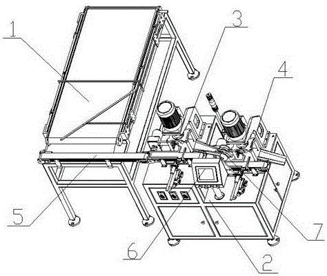
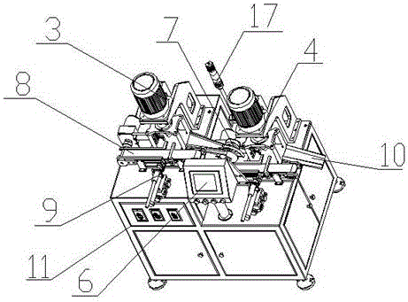
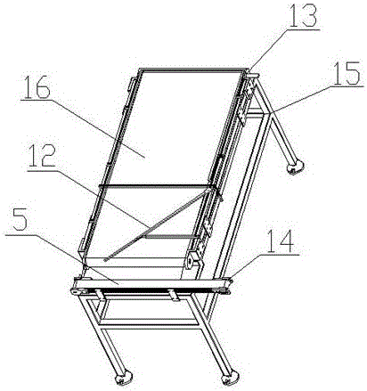
[0020] A magnetic core chamfering machine applied to annular magnetic cores, comprising a feeding and conveying device 1 and a double-sided chamfering device 2, the double-sided chamfering device 2 includes two horizontally placed chamfering devices and a machine tool 11 with the same structure, the chamfering The device is respectively a first chamfering device 3 and a second chamfering device 4, and the plane where the first chamfering device 3 is located is higher than the plane where the second chamfering device 4 is located. The first chamfering device 3 and the second chamfering device 4 The structure is exactly the same and connected by the blanking device 7; the first chamfering device 3 includes the...


PUM


Abstract

The invention relates to the technical field of annular magnetic cores, in particular to a magnetic core chamfering machine applied to an annular magnetic core. The magnetic core chamfering machine comprises a feeding and conveying device and a double-sided chamfering device. The double-sided chamfering device comprises two chamfering device bodies which are horizontally arranged and are of the same structure and a machine tool. The chamfering device bodies are the first chamfering device body and the second chamfering device body. The plane where the first chamfering device body is located is higher than the plane where the second chamfering device body is located. The joint of the first chamfering device body and the second chamfering device body is provided with a discharging device. A flow diversion support is arranged on the upper portion of a first conveyor belt and is of a Z-shaped structure. The magnetic core chamfering machine has the beneficial effects that chamfering can be conducted on the front side, the back side, the inner side and the outer side of a magnetic ring automatically, the workload of workers is lowered greatly, the quality stability of products is guaranteed, the machining efficiency of the products is improved, efficiency and stability are achieved, and all machining processes are completed at a time.

Description

Technical field [0001] The invention involves the field of ring magnetic core technology, which specifically involves a magnetic core inverter applied to the circular magnetic core. Background technique [0002] At present, in the production of the magnetic ring molding stage, even if the craft angle is designed, the sharp part of the backward angle will still occur.When the sharp part is winding in the subsequent coil, it will cut through the insulation layer of the coil, leading to the occurrence of safety accidents; during the spraying process, the corner part of the lacquer is poor, resulting in poor pressure resistance. Therefore, after the formation of the molding suppression is completed, Faltering of the corner of the magnetic ring.However, the inverted angle of the existing large magnetic ring is mainly manual chamfering, and the artificial chamness mainly uses a knife or blade to rotate the corner of the magnetic ring.In this way, processing is time -consuming and labor...

Claims


Application Information

Patent Timeline
Patent Type & Authority Applications(China)
IPC IPC(8): B23D79/00B23Q7/00B23Q3/08
CPCB23D79/00B23Q3/062B23Q3/08B23Q7/00B23Q2703/04
Inventor 韦逢
Owner 日照亿鑫电子材料有限公司
Why Eureka
Try Eureka