Eureka AIR delivers breakthrough ideas for toughest innovation challenges, trusted by R&D personnel around the world.

Metal single-edge crack stress strength factor determining method taking loading machine constraint influence into account

A technology of stress intensity factor and unilateral cracks, which is applied in the direction of testing material strength by applying stable bending force, testing material strength and strength characteristics by applying stable tension/pressure, and achieving reasonable design, strong applicability, and technical solutions puzzle effect

Active Publication Date: 2016-09-07
NORTH CHINA UNIV OF WATER RESOURCES & ELECTRIC POWER
View PDF5 Cites 2 Cited by
  • Summary
  • Abstract
  • Description
  • Claims
  • Application Information

AI Technical Summary

Problems solved by technology

[0003] However, for the tensile testing machine or universal testing machine in domestic laboratories, the upper and lower ends of the machine are generally fixed chucks, which are tightly fixed to the end of the tensile sample, and the line of action of the loading force when the external load changes is always within the size of the specimen. Center, but not always at the center of the ligament length, so that the stretched sample forms an eccentric stress state

Method used


Image

  • Metal single-edge crack stress strength factor determining method taking loading machine constraint influence into account
  • Metal single-edge crack stress strength factor determining method taking loading machine constraint influence into account
  • Metal single-edge crack stress strength factor determining method taking loading machine constraint influence into account

Examples


Embodiment 1

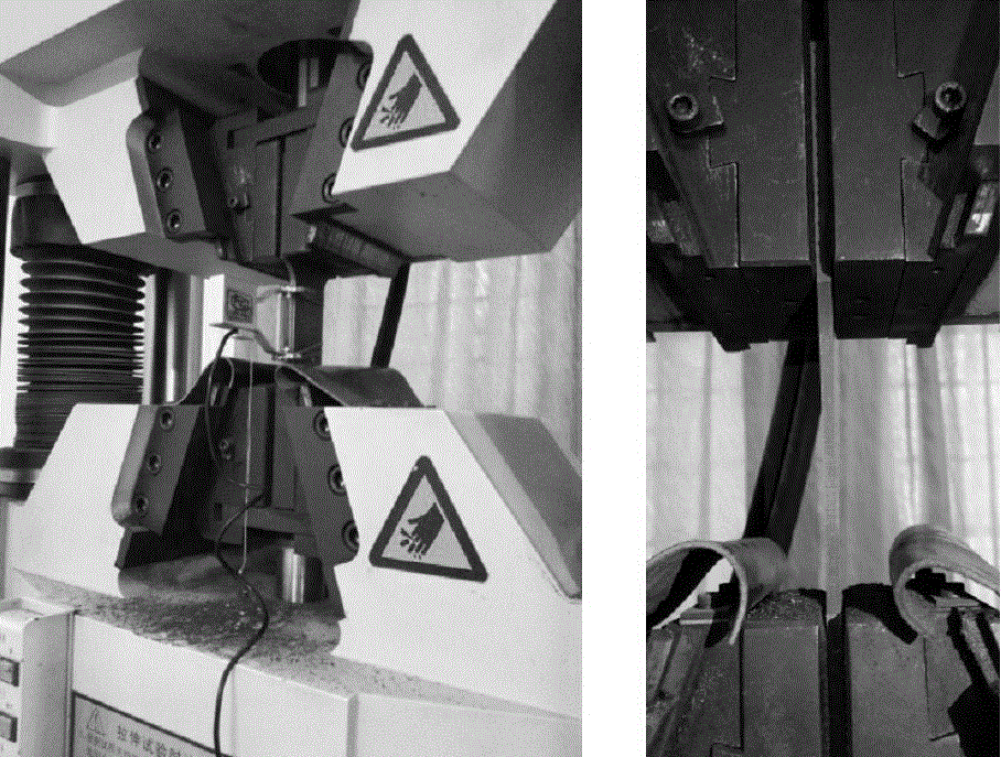
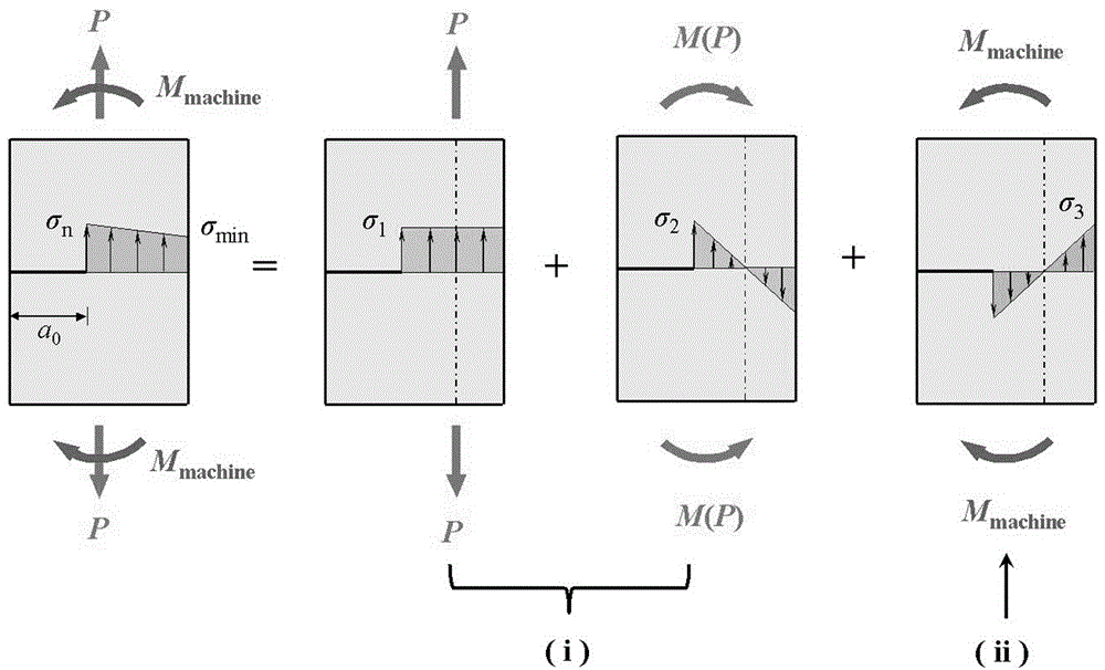
[0046] For tensile testing machines or universal testing machines in domestic laboratories, see figure 1 , the upper and lower ends of the test piece are generally fixed chucks. Due to the strong fixing of the upper and lower ends of the machine, the machine will generate an additional bending moment on the tensile test piece M machine , therefore, if image 3 As shown in , the actual stress on the tensile steel plate with unilateral cracks is divided into two parts: the first part is the axial tensile force of the machine on the specimen, which can be decomposed into an eccentric tensile force P (force over ligament height W - a axis) and a bending moment M ( P ); the second part is the additional bending moment generated by the machine to the specimen to limit the large deformation of the specimen M machine . Due to the superposition of the above two parts of the force, the deformation of the single-side cracked steel plate is very small during the stress process, s...


PUM

PropertyMeasurementUnit
heightaaaaaaaaaa
thicknessaaaaaaaaaa
yield strengthaaaaaaaaaa

Abstract

The invention relates to a metal single-edge crack stress strength factor determining method taking loading machine constraint influence into account. The method comprises the following steps: (1) picking a test piece, measuring the height, which is W, the thickness, which is B, the primary crack length, which is a<0>, and the yield load, which is P; and through the formula (1), obtaining the nominal stress, which is [sigma]<n>, of the test piece by taking the crack into account; (2) by stretching the single-edge crack test piece, obtaining the geometry influence factor Y(i)(a) through a formula (2); (3) by bending the single-edge crack test piece, obtaining the geometry influence factor Y(ii)(a) through a formula (3); (4) substituting the obtained [sigma]<n>, Y(i)(a), and Y(ii)(a) into a formula (4) to obtain the metal single-edge crack stress strength factor K by taking the loading machine constraint influence into account. Because the force loaded on a test piece in a test machine is complicated, the conventional calculation method is imperfect, and the provided method overcomes the shortages.

Description

technical field [0001] The invention belongs to the technical field of performance detection of metal materials, in particular to a method for determining the stress intensity factor of metal unilateral cracks considering the influence of loading machine constraints. Background technique [0002] The physical quantity that reflects the strength of the elastic stress field at the crack tip is called the stress intensity factor. In the mechanical analysis of cracked components, the key step is to calculate the stress intensity factor; the practical method for calculating the stress intensity factor in engineering is mainly to search and calculate from the ready-made stress intensity factor manual. In the current stress intensity factor manual, for the single edge notch test specimen (the single edge notch test specimen) and the single edge notch pure bending specimen (the pure bending specimen), there are its stress intensity factor calculation formula and determination method...

Claims


Application Information

Patent Timeline
Patent Type & Authority Applications(China)
IPC IPC(8): G01N3/08G01N3/20
CPCG01N3/08G01N3/20G01N2203/0017G01N2203/0023G01N2203/0062
Inventor 管俊峰姚贤华胡晓智白卫峰谢超鹏王强
Owner NORTH CHINA UNIV OF WATER RESOURCES & ELECTRIC POWER
Why Eureka
Eureka Blog
Learn More