Ground resistance real-time monitoring device
A technology of real-time monitoring and grounding resistance, applied in the direction of grounding resistance measurement, etc., can solve the problem that the grounding resistance tester cannot achieve real-time monitoring and so on
- Summary
- Abstract
- Description
- Claims
- Application Information
AI Technical Summary
Problems solved by technology
Method used
Image

Examples
Embodiment Construction
[0019] The present invention will be described in detail below in conjunction with the accompanying drawings.
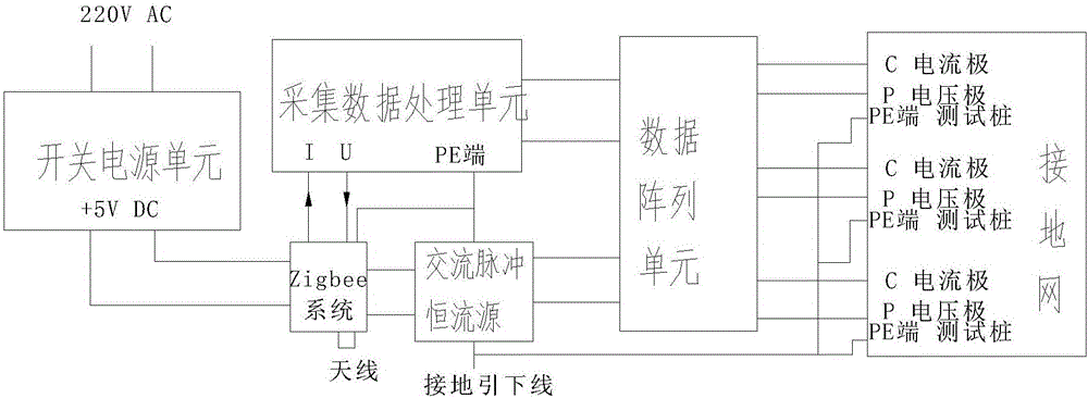
[0020] The real-time monitoring device for grounding resistance of the present invention is composed of five parts, namely: a switching power supply, a ZIGBEE system, an AC pulse constant current source, a data acquisition processing unit, and a data array unit.
[0021] Specifically: the switching power supply can process the mains power into 5V, and output 1A to power the entire system.
[0022] The ZIGBEE system can generate excitation signals, process received data signals, and display and transmit data.
[0023] The AC pulse constant current source can amplify, isolate and filter the excitation signal generated by the ZIGBEE system and output it to the data array unit.
[0024] The acquisition data processing unit can collect, filter, and reshape the voltage obtained between the voltage test electrode and the test ground pile after the signal emitted by the cur...
PUM
 Abstract
Description
Claims
Application Information
PatSnap Eureka turns technology decisions into work you can execute. Powered by our Innovation Knowledge Graph, it runs expert workflows across engineering, life sciences, materials and intellectual property. Get your review-ready output in minutes.


