Wire tidying cutting shafts of a waste wire automatic disassembling device

A technology of waste wires and cutting shafts, which is applied to the recycling of circuits, electrical components, and electronic waste. It can solve the problems of low efficiency of stuck wires and wire management, and achieve the effects of increasing equipment automation, improving work efficiency, and simple structure.

Active Publication Date: 2016-09-07
江苏祥云塑料科技有限公司
View PDF8 Cites 0 Cited by
  • Summary
  • Abstract
  • Description
  • Claims
  • Application Information

AI Technical Summary

Problems solved by technology

However, in the process of automatically straightening, radially cutting, and straightening out the messy and disorganized waste wires into a unified direction and multiple broken wires, problems such as wire jamming and low efficiency of wire management often occur. The wire shearing shaft can increase the automatic disassembly and separation rate of waste wires, improve work efficiency, improve the working environment, save labor costs, prevent dust pollution from dismantling waste cables, and be environmentally friendly and energy-saving; the waste cable dismantling device , the use of adding a cable shearing axis in the cable management mechanism greatly improves the work efficiency of the equipment in automatically sorting messy waste cables.

Method used


Image

  • Wire tidying cutting shafts of a waste wire automatic disassembling device
  • Wire tidying cutting shafts of a waste wire automatic disassembling device
  • Wire tidying cutting shafts of a waste wire automatic disassembling device

Examples


Embodiment Construction

[0016] The present invention will be further described below in conjunction with drawings and embodiments.

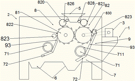
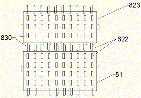
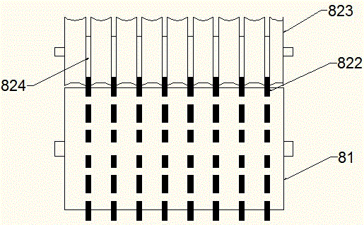
[0017] combine figure 1 and figure 2 , the company has developed an automatic dismantling equipment for waste and old wires, including a frame 1, a body 2, a motor, and a speed controller 3; the motor and the speed controller 3 are linked and installed on the frame 1; 2 The upper part is provided with a feed port 5, and the lower part of the body 2 is provided with a discharge port 6; a wire cutting mechanism 7 is provided in the body 2; it is characterized in that: it also includes a wire management mechanism 8 and a wire feeding mechanism 9; The wire management mechanism 8 includes at least one wire management roller 81, and a hook cutting device 82 cooperating with the wire management roller 81; the speed governor 3 links the wire management roller 81; One side of the wire drum 81 is assembled parallel to the wire drum 81, and at the connection portion of the wire...


PUM


Abstract

The invention provides wire tidying cutting shafts of a waste wire automatic disassembling device. Each wire tidying cutting shaft is arranged behind a wire blocking devices; and the wire tidying cutting shafts and wire tidying rollers are fixedly arranged in a machine body in parallel respectively. The surface of each wire tidying cutting shaft is provided with a cutter structure in close fit with wire tidying hook blades. The surface of each wire tidying cutting shaft is provided with hook blade bulges, which are in close fit with the wire tidying hook blades to form the cutter structure. The wire tidying cutting shaft is of a roller structure and is connected with a speed regulation machine. The circumference surface of each wire tidying cutting shaft is provided with the hook blade bulges, which are in close fit with the wire tidying hook blades to form the cutter structure. The surface of each wire tidying cutting shaft is provided with hook blade grooves for allowing the wire tidying hook blades to pass respectively. The wire tidying hook blades and the hook blade grooves are cooperated closely to form the cutter structure. The wire tidying cutting shaft is of the roller structure and is connected with a speed regulation machine; and the hook blade grooves for allowing the wire tidying hook blades to pass are annularly arranged in the circumference surface of the roller wire tidying cutting shaft, and the wire tidying hook blades and the annular hook blade grooves in the circumference surface of the roller wire tidying cutting shaft are in close fit to form the cutter structure.

Description

technical field [0001] The invention relates to the technical field of separation of metal and plastic in the recycling of urban solid waste resources, belongs to waste wire and cable dismantling machinery, and in particular relates to a wire management and shearing shaft of waste and miscellaneous wire dismantling equipment. Background technique [0002] With the popularization of electronic and electrical products, a large number of waste wires and cables are produced. Due to the large amount of precious metals and plastics in waste wires and cables, the separation and utilization of precious metals and plastics in waste wires and cables has become a high value-added product in urban mining. major social issues. [0003] At present, the dismantling of waste and miscellaneous wires and cables is nothing more than the following: 1. Manual dismantling, low production efficiency, high labor costs, and poor working environment for workers; 2. Incineration method, which damages ...

Claims


Application Information

Patent Timeline
Patent Type & Authority Applications(China)
IPC IPC(8): H01B15/00
CPCH01B15/005Y02W30/82
Inventor 费海英
Owner 江苏祥云塑料科技有限公司
Why Eureka
Try Eureka