Optical carrier suppression-based optical fiber distribution system and method of photo-produced microwave signals

A technology for optically generating microwaves and distribution systems, applied in electromagnetic wave transmission systems, transmission systems, electromagnetic receivers, etc., can solve the problems of increasing circuit noise, limited compensation range of optical fibers, limited compensation range, etc., to achieve fast and accurate compensation range, The effect of breaking through technical difficulties and improving the sensitivity of phase detection

Inactive Publication Date: 2016-09-07
SHANGHAI JIAO TONG UNIV
View PDF2 Cites 18 Cited by
  • Summary
  • Abstract
  • Description
  • Claims
  • Application Information

AI Technical Summary

Problems solved by technology

The optical compensation method mainly relies on the optical delay line. Although it is not limited by the transmission frequency, its compensation range is limited by the length of the optical fiber in the delay module, and the response speed is relatively slow.
The methods of electrical compensation mainly include the method of electric delay line and frequency mixing. The electric delay line method is also limited by the compensation range. Although the frequency mixing method can avoid the design of the circuit, it needs to increase the

Method used


Image

  • Optical carrier suppression-based optical fiber distribution system and method of photo-produced microwave signals
  • Optical carrier suppression-based optical fiber distribution system and method of photo-produced microwave signals
  • Optical carrier suppression-based optical fiber distribution system and method of photo-produced microwave signals

Examples


Embodiment Construction

[0043] The present invention will be described in detail below in conjunction with specific embodiments. The following examples will help those skilled in the art to further understand the present invention, but do not limit the present invention in any form. It should be noted that those skilled in the art can make several changes and improvements without departing from the concept of the present invention. These all belong to the protection scope of the present invention.

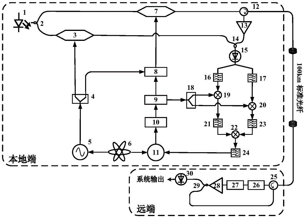
[0044] according to figure 1Shown is a block diagram of a distribution system for optically generated microwave signals based on optical carrier suppression. This invention requires a fiber laser 1, a first optical coupler 2, a first Mach-Zehnder modulator 3, a first power divider 4, and a microwave signal of 10 GHz Generator 5, 10MHz rubidium clock source 6, second Mach-Zehnder modulator 7, single sideband modulator 8, 35MHz voltage controlled oscillator 9, loop filter 10, digital frequency and phase d...


PUM

PropertyMeasurementUnit
Line widthaaaaaaaaaa

Abstract

The present invention provides an optical carrier suppression-based optical fiber distribution system and method of photo-produced microwave signals. The optical carrier suppression-based optical fiber distribution system of the photo-produced microwave signals includes a photo-produced microwave signal module, a phase detection module, a phase compensation module and a system output module; the photo-produced microwave signal module generates signal light which is required to be transmitted to a remote end and local light which serves as reference; the phase detection module detects phase jitter caused by optical fiber link jitter and obtains corresponding phase information; the phase compensation module controls the output of a voltage-controlled oscillator according to the phase information, and performs single-sideband modulation on the microwave signals outputted by a microwave signal generator through the output signals of the voltage-controlled oscillator, and then generates compensation signals; and the system output module outputs signals light which has been subjected to phase compensation. With the system and method of the invention adopted, phase detection sensitivity is increased to a magnitude order of light wavelength; technical difficulty in live operation-based high-frequency microwave mixing can be eliminated; a phase-locked loop is adopted to carry out feedback control on obtained phase error signals; and a phase compensation mechanism is fast and accurate, and is not limited in compensation scope.

Description

technical field [0001] The present invention relates to the technical field of optically generated microwave signal distribution, in particular to an optical fiber distribution system and method for optically generated microwave signals based on optical carrier suppression. Background technique [0002] The local oscillator reference signal distribution technology is a kind of transmission of highly stable local reference signals to remote users through optical fiber links. The reference signals recovered by remote users need to be highly coherent with the local reference signals. The core technology is how to eliminate Additional noise due to fiber link jitter. [0003] Phase error compensation caused by optical fiber link jitter is mainly divided into optical compensation method and electrical compensation method. The optical compensation method mainly relies on the optical delay line. Although it is not limited by the transmission frequency, its compensation range is lim...

Claims


Application Information

Patent Timeline
IPC IPC(8): H04B10/2543H04B10/2569H04B10/61
CPCH04B10/2543H04B10/2569H04B10/6163H04B10/6165
Inventor 王小成刘张唯一邓楠孙东宁董毅
Owner SHANGHAI JIAO TONG UNIV
Why Eureka
Try Eureka