Automatic control method for light carrier inhibition zero return code modulator

A technology of optical modulators and modulators, applied in electromagnetic wave transmission systems, electrical components, transmission systems, etc., can solve the problems of complex modulation control, etc., achieve the effect of constant eye diagram shape, stable eye diagram shape, and guaranteed extinction ratio

Inactive Publication Date: 2012-05-30
宁波春天通信工业有限公司
View PDF0 Cites 0 Cited by
  • Summary
  • Abstract
  • Description
  • Claims
  • Application Information

AI Technical Summary

Problems solved by technology
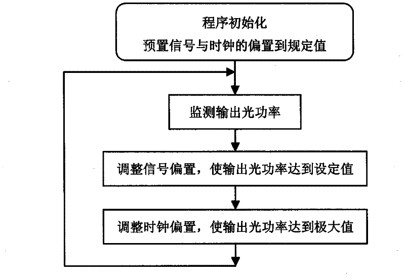
However, for the carrier suppression return-to-zero code, because two-level modulation is required, and the signals between the two-level modulation need to maintain a certain correlation, this causes the complexity of the modulation control, and the original method of controlling the stability of the output optical power is no longer applicable to this modulation

Method used


Image

  • Automatic control method for light carrier inhibition zero return code modulator
  • Automatic control method for light carrier inhibition zero return code modulator
  • Automatic control method for light carrier inhibition zero return code modulator

Examples


Embodiment 1

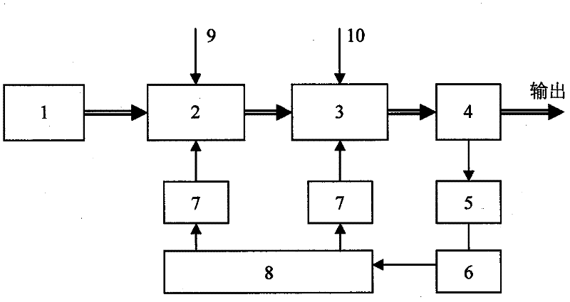
[0019] Embodiment one: if figure 2 As shown, this is a typical suppressed return-to-zero code modulator for single-stage monitoring. The modulator mainly includes a DC light source 1, a signal light modulator 2, and a half-rate clock light modulator 3. After the half-rate clock light modulator 3, a The optical coupler 4 and the optical power detector 5, the optical power detector 5 is connected with the single-chip microcomputer 8 through the analog-to-digital conversion circuit 6, and the single-chip microcomputer 8 is respectively connected with the first bias signal generating circuit 9 of the signal optical modulator 2 through the digital-to-analog conversion circuit 7 It is connected with the second bias signal generating circuit 10 of the half-rate clock optical modulator 3. The DC light source 1 is usually a laser, and the optical signal output by it is sent to the signal optical modulator 2, and the signal optical modulator 2 passes the modulation signal to the signal ...

Embodiment 2

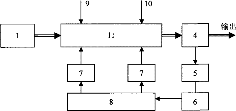
[0020] Embodiment two: if Figure 6 As shown, the difference from Embodiment 1 is that a signal optical power detector is integrated in the signal optical modulator 21, and a clock optical power detector is integrated in the half-rate clock optical modulator 31. The modulator with this structure can The output optical powers of the signal optical modulator 21 and the half-rate clock optical modulator 31 are respectively detected and automatically controlled. The two-stage modulator for detecting optical power is also based on the output optical signal of the DC light source 1, and sends it to the signal optical modulator 21, and modulates the optical signal into a non-return-to-zero optical signal through the modulation signal. The output non-return-to-zero code optical signal is sent to the half-rate clock optical modulator 31, and the half-rate clock optical modulator 31 modulates the non-return-to-zero code optical signal into an optical signal that suppresses the return-to...


PUM


Abstract

The invention discloses an automatic control method of an optical carrier suppression return-to-zero modulator. The modulator mainly comprises a DC light source, a signal optical modulator and a half-speed clock optical modulator, and is characterized in that the modulator mainly is provided with a single chip microcomputer and a photoelectric detector; the photoelectric detector detects a light signal and outputs a detection electrical signal which is subjected to the analog-digital conversion and then is delivered to the single chip microcomputer; the single chip microcomputer processes thedetection electrical signal and performs the digital-analog conversion of control signals respectively according to the preset program and then transmits the signals to a first offset signal generating circuit and a second offset signal generating circuit; and the first and the second offset signal generating circuits keep the power of the output light signals stable at the preset peak power. Theautomatic control method has the advantages as follows: based on the basic optical carrier suppression return-to-zero modulation code circuit and the control of the output light power, the method analyzes and distinguishes the change characteristics of the output light power to control the offset voltage of the signal light modulator and the offset voltage of the half-rate clock signal of the clock light modulator, respectively, thereby ensuring the stability and the reliability of the output light signal code type.

Description

technical field [0001] The invention relates to a stable control method for optical communication transmission signals, in particular to an automatic control method for an optical carrier suppression return-to-zero code modulator. Background technique [0002] The easiest way to use optical signals to transmit digital signals is to represent the signal "1" with light, and the signal "0" without light. This digital optical signal transmission pattern is widely used in the current optical communication field due to its simple technical method and low cost, and is called non-return-to-zero code (NRZ). It can be realized simply by directly modulating the light source, or by using an external modulator. However, with the increase of transmission rate and transmission distance, the weakness of this transmission pattern is rapidly highlighted. Compared with return-to-zero code (RZ) and carrier-suppressed return-to-zero code (CSRZ), its carrier efficiency, nonlinear threshold and ...

Claims


Application Information

Patent Timeline
Patent Type & Authority Patents(China)
IPC IPC(8): H04B10/12H04B10/17H04B10/294
Inventor 张永成崔思健邓明赵毅
Owner 宁波春天通信工业有限公司
Why Eureka
Try Eureka