Microwave ionization type plasma thruster

A plasma and thruster technology, applied in the field of ions, can solve the problems of inability to meet the thrust demand and the thrust variation range of the thruster is small, and achieve good ionization effect, high power coefficient and high ionization degree.

Active Publication Date: 2016-09-07
台州星空智联科技有限公司
View PDF5 Cites 21 Cited by
  • Summary
  • Abstract
  • Description
  • Claims
  • Application Information

AI Technical Summary

Problems solved by technology

Under the fixed structure, the thrust range of the propeller is smal

Method used


Image

  • Microwave ionization type plasma thruster
  • Microwave ionization type plasma thruster
  • Microwave ionization type plasma thruster

Examples


Embodiment Construction

[0019] The present invention will be further described below in conjunction with accompanying drawing:

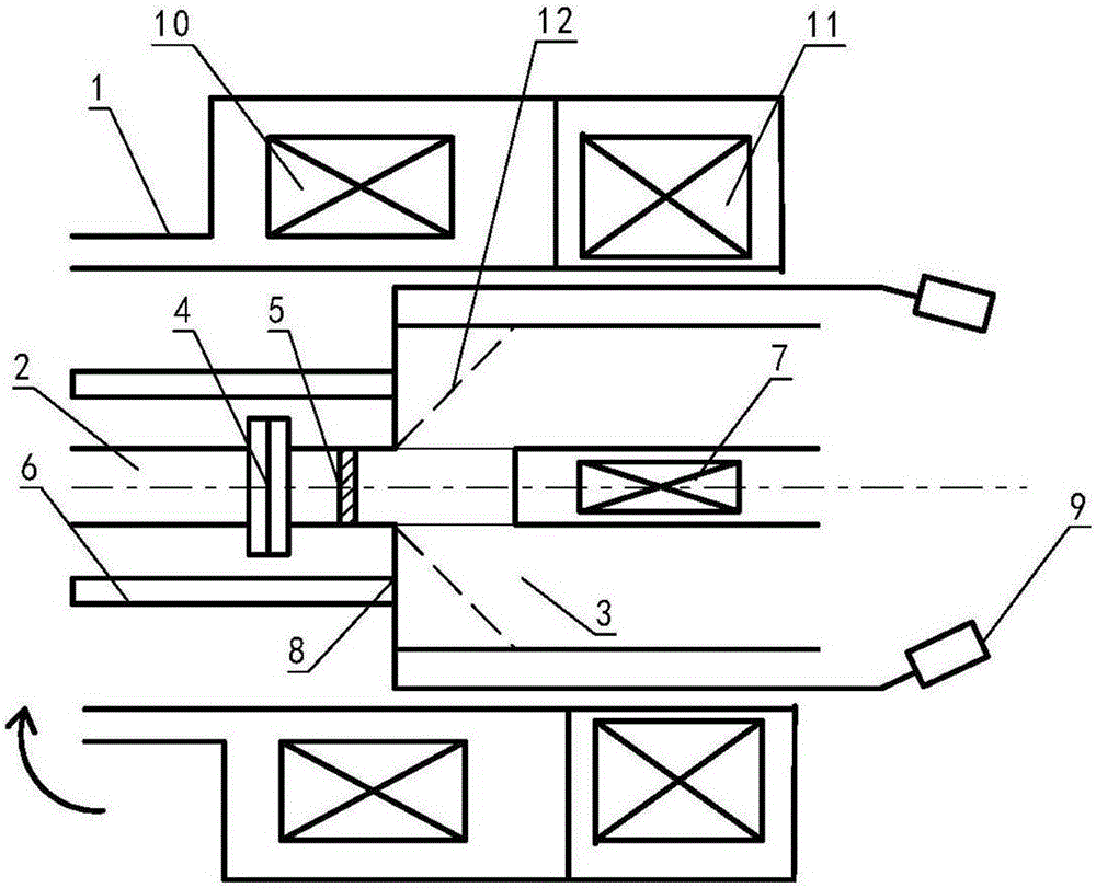
[0020] Such as figure 1 As shown, the present invention mainly includes a tubular shell 1, a circular waveguide 2 and a tubular working cavity 3, the central axis of the front end of the tubular working cavity is connected to the waveguide, and a coupler 4 is arranged on the waveguide and a ceramic window 5; a gas introduction tube 6 is provided on the periphery of the waveguide, and the gas introduction tube communicates with the working cavity, and a group of magnetic field inner coils 7 are installed at the central axis position inside the working cavity; the front end plate of the working cavity is an anode Plate 8, the tail end of the working chamber adopts a shrinking structure, and the tail end is connected to the emission cathode 9;

[0021] The tubular casing is installed outside the working chamber, and the resonant magnetic field coil 10 and the rotating magneti...


PUM


Abstract

The invention discloses a microwave ionization type plasma thruster. The microwave ionization type plasma thruster comprises a tubular enclosure, a circular waveguide tube and a tubular working cavity. The waveguide tube is connected with the position of the central axis at the front end of the tubular working cavity. A coupler and a ceramic window are arranged on the waveguide tube. Gas importing tubes are arranged at the periphery of the waveguide tube. The gas importing tubes are connected with the working cavity. A set of intra-magnetic filed coils are mounted at the position of the central axis in the working cavity. The front end panels of the working cavity are anode plates. A throat structure is employed at the tail end of the working cavity. The tail end is connected with emitting cathodes. The tubular enclosure is mounted at external part of the working cavity. Resonant magnetic field coils and rotating magnetic field coils are mounted on the enclosure in a front and back sequence. The rotating magnetic field coils are close to the tail end of the working cavity. The rotating magnetic field coils are movably mounted on the enclosure and can rotate under drive of a motor. The plasma thruster has the advantages that the thrust amplitude is adjustable, and the ionization and acceleration processes are separately operated.

Description

technical field [0001] The invention relates to the field of plasma technology, in particular to a novel microwave ionization type plasma thruster. Background technique [0002] Space propulsion technology is mainly divided into four categories: conventional chemical propulsion, electric propulsion, micro propulsion and new type propulsion. Among them, a large number of successful applications of electric propulsion on various satellites and deep space probes have proved its advantages and reliability, and its application will continue to expand. Electric propulsion refers to the technology of generating thrust by heating, dissociating and accelerating working fluid with electric energy to form a high-speed jet. The main advantages of the electric propulsion system are: high specific impulse, long life, repeatable start, small thrust and high control precision. The application of electric propulsion in artificial earth satellites and interplanetary vehicles can significant...

Claims


Application Information

Patent Timeline
IPC IPC(8): H05H1/24F03H1/00
CPCF03H1/0081H05H1/24
Inventor 王春生王华山王义德陈庆杰杨丹
Owner 台州星空智联科技有限公司
Why Eureka
Try Eureka