Dielectric barrier discharge ionization, analytical instrument and ionization method

a technology of dielectric barrier and discharge ionization, applied in the field of ion analysis devices, can solve the problems of difficult low-pressure work, difficult to ignite common dielectric barrier discharge ionization, and difficult spectrum interpretation, and achieve simple and ingenious design and stable signal

Pending Publication Date: 2021-11-11
SHIMADZU CORP
View PDF0 Cites 3 Cited by
  • Summary
  • Abstract
  • Description
  • Claims
  • Application Information

AI Technical Summary

Benefits of technology

[0043]The above mass spectrometer operates without the assistance of the carrier gas. The pressure of the ion source is controlled by using the preceding stage of the mass spectrometer. A relatively higher vacuum level can promote the semi-permeable m

Problems solved by technology

Furthermore, common dielectric barrier discharge ionization is hard to be ignited and is difficult to work at low pressure.
However, currently for ion sources under low-pressure operating environment, either the suitable pressure range is narrow or an ideal ionization feature is not reached.
0.01-1 Pa: A typical choice in this pressure range is electron impact ion source. However, strong electron impact can produce more fragment ions and make the spectrum hard to be interpreted; and the filament is easily burnt out at an pressure above 1 Pa, which affects the lifetime

Method used


Image

  • Dielectric barrier discharge ionization, analytical instrument and ionization method
  • Dielectric barrier discharge ionization, analytical instrument and ionization method
  • Dielectric barrier discharge ionization, analytical instrument and ionization method

Examples


first embodiment

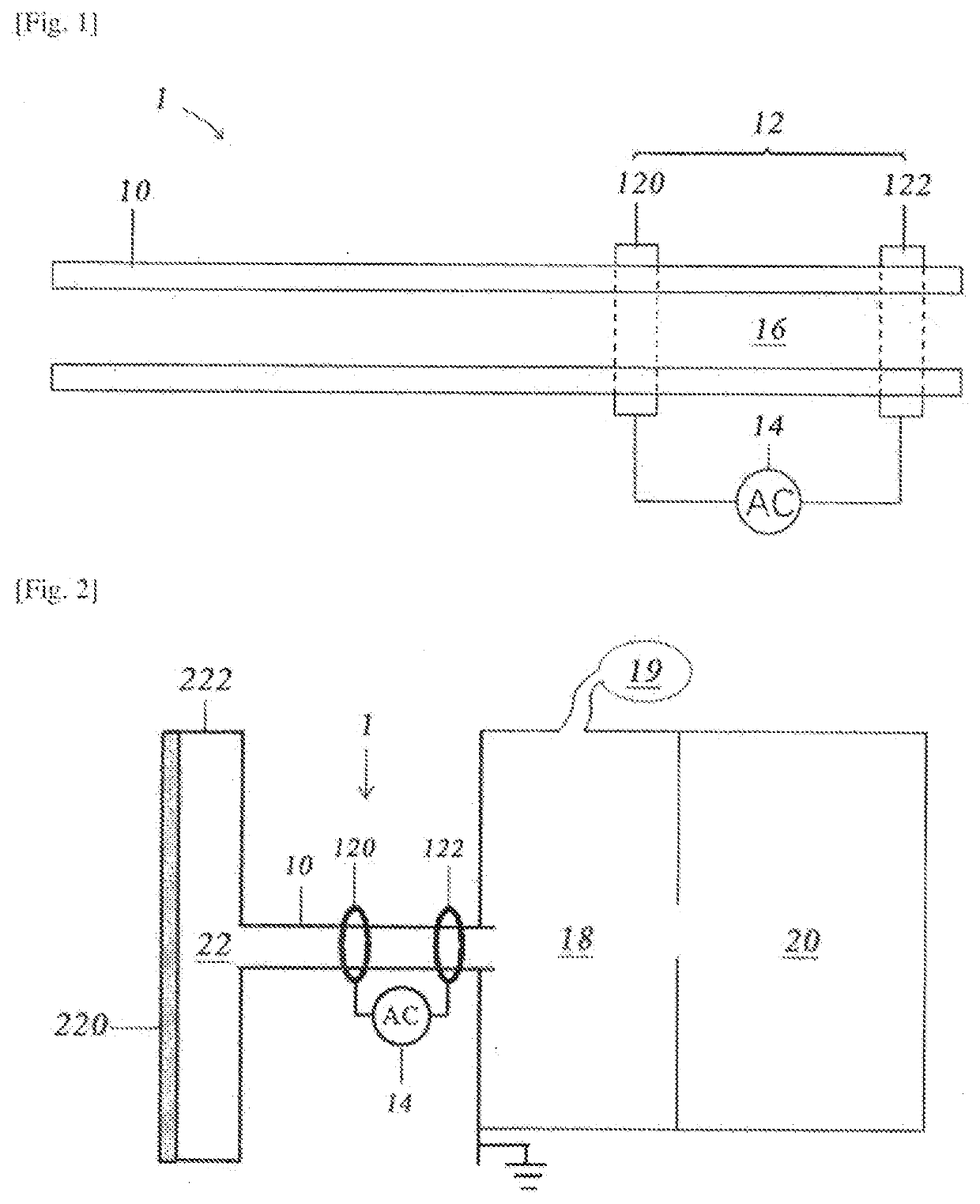
[0052]As shown in FIG. 1, the first embodiment provides dielectric barrier discharge ionization 1. A dielectric barrier discharge tube 10 used by the dielectric barrier discharge ionization is a capillary tube. A pair of annular electrodes 12 (including a first electrode 120 and a second electrode 122) respectively wrap the surface of the outer wall at different positions along the axial direction of the capillary tube, and is arranged coaxially with the dielectric barrier discharge tube 10. An alternating current of 0.2 to 3 MHz can be powered on between the first electrode 120 and the second electrode 122 of the annular electrode 12. The waveform of the alternating current can be a sine wave, a square wave, a sawtooth wave, a step wave, a triangular wave, a pulsedwave or other suitable waveforms. The peak-to-peak amplitude is 100 to 10,000 V. In the present embodiment, the alternating current between the annular electrodes 12 adopts a sinusoidal waveform alternating current of 2.5...

second embodiment

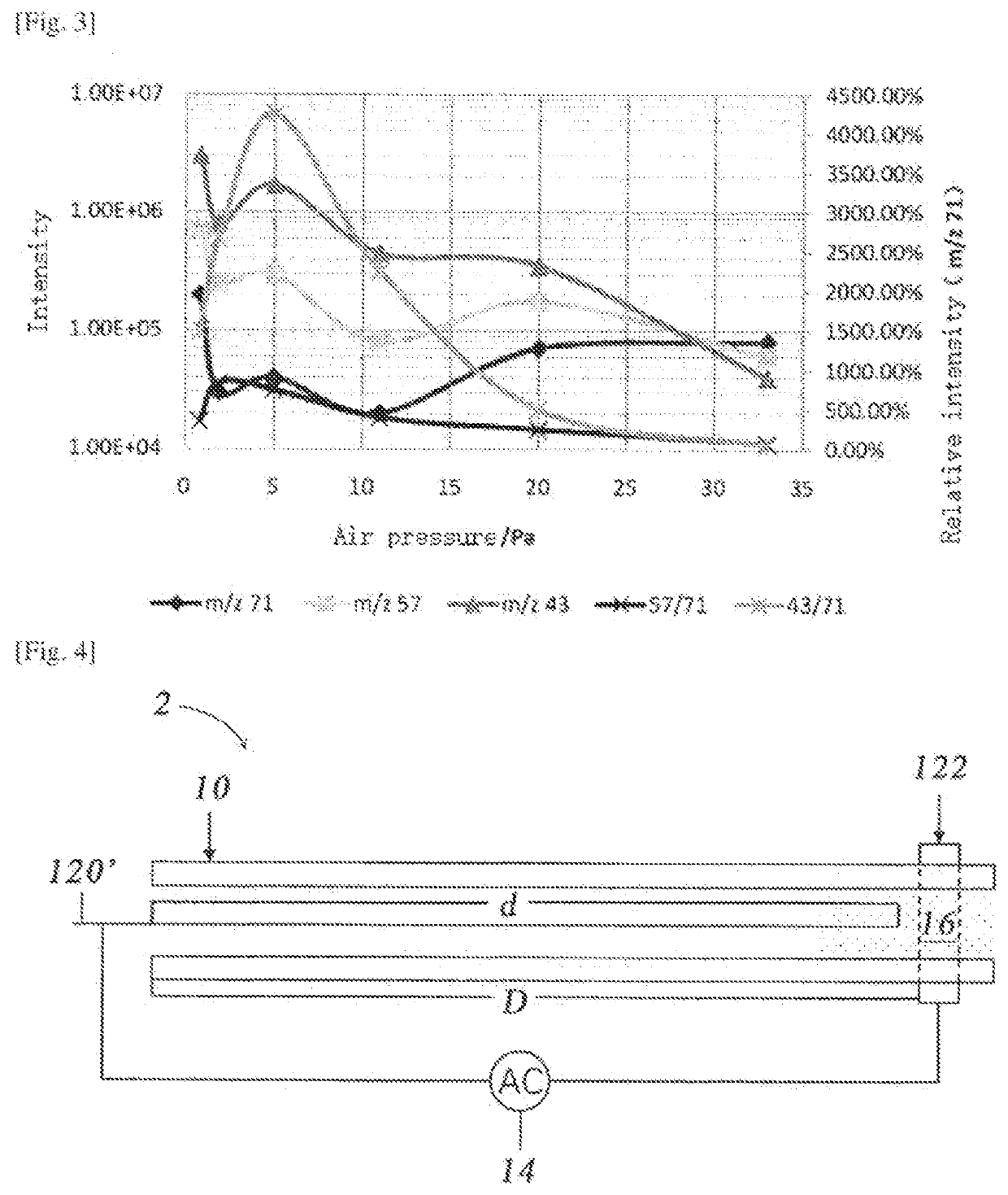
[0067]As shown in FIG. 4, the present embodiment provides an annular dielectric barrier discharge ionization 2, including a dielectric barrier discharge tube 10, an electrode pair consisting of a first electrode 120′ and a second electrode 122, in which an alternating voltage is provided between the first electrode 120′ and the second electrode 122 by an alternating current source 14, and each parameter of the alternating voltage is the same as in the first embodiment. In the embodiment, the dielectric barrier discharge tube 10 is a capillary tube in which the inner diameter is 0.2 mm and the wall thickness is 0.4 mm.

[0068]In the embodiment, the first electrode 120′ is a needle-like electrode with one end thereof extending into the dielectric barrier discharge tube 10, and the extending depth d is smaller than the depth D of the abutting position where the second electrode 122 abuts the dielectric barrier discharge tube 10, that is, the first electrode 120′ cannot reach the abutting...

third embodiment

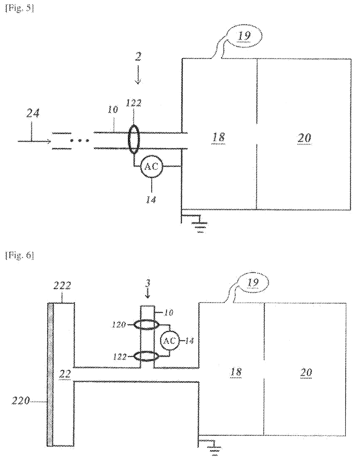
[0072]The present embodiment provides a mass spectrometer which is relatively similar to that in the first embodiment but have a different sample introduction structure. As shown in FIG. 6, the mass spectrometer uses a sample inlet 22 coated with a semipermeable membrane 220. However, after the sample introduction in the embodiment, instead of directly entering the ionization region of the dielectric barrier discharge ionization 3 to mix with the plasma, the ionized substance outlet of the dielectric barrier discharge tube 10, that is, the lower port of the dielectric barrier discharge tube 10, is provided downstream of the sample inlet 22 along the sample delivery direction, so that the sample can mix with and be ionized by the ionized substance flowing out of the ionized substance outlet.

[0073]In the above manner, the mass spectrometer structure provided by the embodiment can prevent the sample from directly interacting with the electrons in the discharge plasma, which results in ...


PUM


Abstract

The present invention provides dielectric barrier discharge ionization, including a dielectric barrier discharge tube and an electrode pair consisting of a first electrode and a second electrode. At least a portion of the dielectric barrier discharge tube is provided between the first electrode and the second electrode. The electrode pair can ionize the sample after the power is turned on. The dielectric barrier discharge tube is in communication with a vacuum portion. The pressure range in the dielectric barrier discharge tube is 0.01 to 100 Pa. The dielectric barrier discharge ionization provided by the invention remedies the defects of existing low-pressure ion sources in the pressure range, and provides the low-pressure ion source with high ionization ability, high versatility and simple devices.

Description

TECHNICAL FIELD[0001]The invention relates to the field of ion analysis devices, in particular to an ion source, a mass spectrometer or an ion mobility spectrometer with the ion source, and a corresponding ionization method.BACKGROUND ART[0002]In mass spectrometric analysis, the atmospheric ionization technique is characterized in that the ionization of a sample molecule to be detected can be realized under open conditions, and a surface sample is directly subjected to mass spectrometric analysis. With years of developments, novel ambientionization technologies have been quite varied, and mass spectrometry analysis methods with different features have been established. In 2007, a novel atmospheric ionization technique, that is, the dielectric barrier discharge ionization (DBDI), was developed by the Zhang Xinrong Research Group of Tsinghua University.[0003]The dielectric barrier discharge (DBD), also known as the silent discharge, is annonequilibrium gas discharge with an insulating...

Claims


Application Information

Patent Timeline
IPC IPC(8): H01J49/16H01J49/26H01J49/04
CPCH01J49/16H01J49/04H01J49/26H01J49/10H01J49/168
Inventor LIN, YIMINGSUN, WENJIAN
Owner SHIMADZU CORP
Why Eureka
Try Eureka