
Novel chamber type pressure filter

A box-type filter press, a new type of technology, applied in the direction of filtration separation, separation methods, chemical instruments and methods, etc., can solve problems such as incomplete solid-liquid separation, blockage of filter cloth mesh, and reduced work efficiency, so as to reduce labor costs and maintenance costs, convenient filter cake discharge, and improved work efficiency

Inactive Publication Date: 2016-09-21
苏州志英明建信息科技有限公司
View PDF5 Cites 8 Cited by
  • Summary
  • Abstract
  • Description
  • Claims
  • Application Information

AI Technical Summary

Problems solved by technology

[0003] Since the filter unit is pressed by the pressing plate at one end of the filter press, the closer to the end of the thrust plate, the greater the resistance, the smaller the pressure, the worse the pressing effect, and the incomplete solid-liquid separation, so it is necessary to adjust the position of the filter plate and start again. Compression work wastes manpower and material resources and reduces work efficiency; in the process of filter pressing, the pressure of the feed pump is used to perform press filtration, the dehydration effect is not good, and the filter plate is easy to deform. At the same time, the filter cloth directly contacts the material, which is easy to cause filtration The mesh of the cloth is clogged, and the drainage effect is not good. After each use, the filter cloth needs to be removed and cleaned. It is troublesome to disassemble and the filter cloth is easily damaged.

Method used


Image

  • Novel chamber type pressure filter
  • Novel chamber type pressure filter
  • Novel chamber type pressure filter

Examples


Embodiment Construction

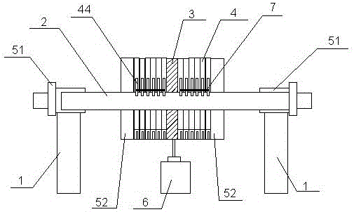
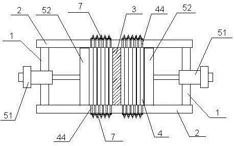
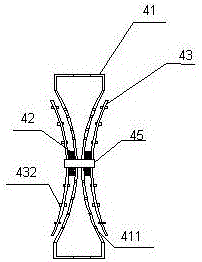
[0020] As shown in the figure, a new box filter press according to the present invention includes a bracket 1, two beams 2, a thrust plate 3, a filter unit 4, a pressing device 5, a feed pump 6 and a tie rod device 7 , two beams 2 are arranged parallel to each other on the support 1, the front and rear ends of the thrust plate 3 are respectively fixed in the middle of the two beams 2, and the bottom of the thrust plate 3 is provided with a feed port, The left and right side walls are provided with a discharge port, the feed pump 6 is connected to the feed port of the thrust plate 3, and the left and right sides of the thrust plate 3 are respectively provided with several The filter unit 4 parallel to the plate 3 is connected by a pull rod device 7 between several filter units 4, and the left and right ends of the support 1 are respectively provided with a pressing device 5, and the pressing device 5 includes a hydraulic structure 51 and a pusher Plate 52, the hydraulic structu...


PUM


Abstract

The invention relates to a novel chamber type pressure filter. The novel chamber type pressure filter comprises a bracket, two cross beams, a thrust plate, a filtering unit, compressing devices and a feeding pump, wherein the two cross beams are arranged on the bracket and parallel to each other; the front end and the rear end of the thrust plate are fixedly arranged in the middle parts of the two cross beams; a feeding opening is formed in the bottom part of the thrust plate, and discharging openings are formed in the left sidewall and the right sidewall of the thrust plate; the feeding pump is connected with the feeding opening of the thrust plate; a plurality of filtering units are correspondingly arranged at the left side and the right side of the thrust plate, and the filtering units are parallel to the thrust plate and connected through pulling rod devices; the compressing devices, which can push the filtering unit to horizontally move on the cross beams, are arranged at the left end and the right end of the bracket. The novel chamber type pressure filter has the beneficial effects that the structure is simple, the extruding dewatering capacity is high, a filter cloth is prevented from being frequently replaced, a filtering plate is low in possibility of being deformed, and a filter cake can be conveniently discharged; the labor cost and the repair cost can be effectively decreased, and the working efficiency can be improved.

Description

technical field [0001] The invention relates to the field of ceramic production equipment, in particular to a novel chamber filter press. Background technique [0002] In the ceramic production process, a very important step is to press filter the mud mixed with the ball mill powder, and use the filter press equipment to separate the solids and water. Filter press equipment includes chamber filter press, vertical filter press and plate filter press. Chamber filter press has the advantages of less loss during feeding, fast filtration speed, high temperature and high pressure resistance, good sealing performance, uniform filter cake washing, and low moisture content. It is widely used in all solid-liquid separation industries. The current box-type filter press has a frame, the frame has a main beam, one end of the main beam has a hydraulically driven compression plate, the other end of the main beam has a thrust plate, and the main beam has a filter press device. It is a plu...

Claims


Application Information

Patent Timeline
Patent Type & Authority Applications(China)
IPC IPC(8): B01D25/12B01D25/34
CPCB01D25/12B01D25/34
Inventor 马志明
Owner 苏州志英明建信息科技有限公司
Learn More