Reservoir underwater walking sand suction and discharge device

A walking type and reservoir technology, which is applied in water conservancy projects, sea area projects, earth movers/excavators, etc., can solve problems such as small operation range, endangering residents' lives and property, and erosion, so as to expand the space operation area, High efficiency of sand suction and dredging, and the effect of improving practicability

Active Publication Date: 2016-09-21
CHANGJIANG RIVER SCI RES INST CHANGJIANG WATER RESOURCES COMMISSION
View PDF8 Cites 11 Cited by
  • Summary
  • Abstract
  • Description
  • Claims
  • Application Information

AI Technical Summary

Problems solved by technology

Reservoir siltation will reduce the effective storage capacity of the reservoir area, directly affecting the normal performance of the reservoir's flood control and power generation functions. What is more prominent is that the loss of the reservoir's water supply function will pose a threat to food security and bring huge economic losses to rural people.
After the reservoir intercepts the sediment, the sediment carried by the downstream water flow will directly reduce, and the downstream riverbed will be scoured, causing the river bank to collapse, the riverbed to cut down, and cause a series of problems, such as causing the failure of the original water diversion project, affecting shipping, and endangering bridges and embankments. The safety of river buildings, even endangering the lives of residents and their properties
Aiming at the problem of reservoir sediment, most reservoirs discharge the reservoir sediment to the downstream through sand discharge holes. This method consumes a lot of water, has a limited range of sand removal, and has a certain impact on the water supply and power generation efficiency of the reservoir.
Some lake-type reservoirs blindly build sand-drawing caves, and the sand-drawing effect is poor
In addition, many reservoirs built in the last century were not designed with sand discharge holes
[0003] Mechanical dredging is one of the most effective ways to remove sediment from reservoirs. Common dredging machinery includes dredgers and hydraulic dredging systems. Among them, dredgers have high operating costs and relatively small operating ranges.
Regarding siphon hydraulic dredging, related research has been carried out in China. For example, Chinese patents such as CN103321179A, CN101372835A, CN1022639C, CN101644042A, and CN85203938U have disclosed the method of using the siphon effect of the head difference between the upstream and downstream of the dam to suck the silt from the reservoir. It is worth noting that most inventions about hydraulic dredging do not consider the characteristics of reservoir silt consolidation, and the poor transportation conditions of mountainous reservoirs have the following problems and deficiencies: (1) most hydraulic dredging devices are not Considering the sand washing equipment, it is difficult to cause high-concentration muddy water in the actual operation process, and the dredging efficiency is low; (2) a few devices have considered mechanical sand winches such as plow heads, rake wheel nail teeth, etc., but the addition of this device leads to The weight of the entire suction head device is increased, and the control requirements for the movement of the suction head are greatly improved; (3) Most hydraulic dredging devices directly use multiple sets of control boats and winches to control the underwater suction head movement of the suction head, and the overall structure is relatively bulky, not easy to use. Suitable for mountainous reservoirs with poor transportation conditions

Method used


Image

  • Reservoir underwater walking sand suction and discharge device
  • Reservoir underwater walking sand suction and discharge device
  • Reservoir underwater walking sand suction and discharge device

Examples


Embodiment Construction

[0022] The technical solutions in the present invention will be clearly and completely described below in conjunction with the accompanying drawings in the present invention.

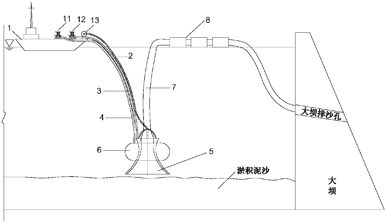
[0023] Please refer to figure 1 , The underwater walking sand suction and discharge device for the reservoir of the present invention includes a working boat 1, a traction steel rope 2, a water filling pipe 3, an air filling pipe 4, a porous sand suction table 5, an annular air cavity 6, a sand conveying pipe 7, and a buoy 8.

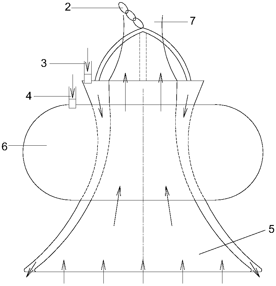
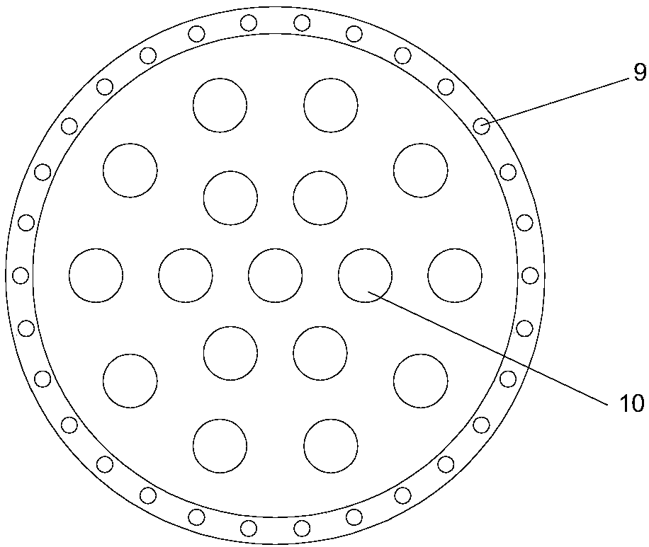
[0024] The working boat 1 is placed on the water surface of the reservoir, and the working boat 1 is provided with a water pump 11, an air pump 12, a winch 13 and a positioning system. The porous sand suction tray 5 is arranged on the sedimentation bed surface at the bottom of the reservoir, such as figure 2 and image 3 As shown, the porous sand-absorbing tray 5 is approximately in the shape of an inverted funnel, the disc surface diameter of the chassis is not less than 100c...


PUM


Abstract

The invention provides a reservoir underwater walking sand suction and discharge device. The device comprises a working ship, a water pump, an air pump, a windlass and a positioning system arranged on the working ship, and a porous sand suction disc arranged on a silting bed surface of the bottom of a reservoir. An annular air cavity is formed in the porous sand suction disc; a sand punching hole and a sand suction hole are formed in the porous sand suction disc; the water pump is communicated with the sand punching hole through a water charging pipe; the sand suction hole is connected into a dam sand discharge hole through a sand conveying pipe; the air pump is communicated with the annular air cavity through an inflation pipe; and the windlass is connected with the porous sand suction disc through a traction steel rope. The device is arranged in a reservoir area; high-pressure water is injected in the sand punching hole of the porous sand suction disc through the water pump for dispersing and disturbing silted sediments of the reservoir; a high-concentration water and sand mixture is sucked through the sand suction hole of the porous sand suction disc and the sand conveying pipe for realizing efficient dam passing of the silted sediments of the reservoir; the dispersion, the disturbance and the suction of the silted sediments at the bottom of the reservoir can be synchronously realized; high-concentration muddy water is easy to form; the water consumption is low; and the sand sucking and desilting efficiency is high.

Description

technical field [0001] The invention relates to the field of collection and treatment of reservoir sediment, in particular to an underwater walking sand suction and discharge device for reservoirs. Background technique [0002] Reservoirs are one of the most important water conservancy projects. According to the statistics of the Ministry of Water Resources, as of 2008, 86,353 reservoirs of various types have been built nationwide, with a total storage capacity of 692.4 billion m 3 . The large-scale construction of reservoirs has greatly improved the flood control capacity of rivers, exerted huge benefits in water supply and power generation, and played a very important role in people's production and life as well as social and economic development. While the reservoir is in operation, problems such as sediment deposition in the reservoir area and clean water scouring downstream will inevitably occur. According to the survey data in 1992, a total of 11,931 reservoirs were...

Claims


Application Information

Patent Timeline
Patent Type & Authority Applications(China)
IPC IPC(8): E02B3/02E02F5/28E02F3/88E02F3/92
CPCE02B3/023E02F3/8875E02F3/92E02F3/9293E02F5/28
Inventor 杨文俊曹慧群李青云魏国远江耀祖黄仁勇李健陈锦
Owner CHANGJIANG RIVER SCI RES INST CHANGJIANG WATER RESOURCES COMMISSION
Why Eureka
Try Eureka