Prefabricated steel structure framework system

A steel structure frame and assembly technology, applied in the field of steel structure frames, can solve the problems of easy buckling of ordinary steel plate shear walls, large cross-sectional size of ordinary steel beams and steel columns, buckling of ordinary steel plate shear walls, etc. Post-repair, improved space utilization, and good energy consumption performance

Active Publication Date: 2016-09-21
SHANDONG ZHONGTONG STEEL STRUCTURE ENG
View PDF12 Cites 7 Cited by
  • Summary
  • Abstract
  • Description
  • Claims
  • Application Information

AI Technical Summary

Problems solved by technology

[0004] In the seismic design of frame structures, ordinary steel plate shear walls are prone to buckling under earthquake reciprocating tension and compression loads, which affects their energy dissipation performance
Chinese Patent No. CN201510067841.9 discloses an invention patent titled "An Assembled Energy-Dissipating Steel Plate Shear Wall"; Chinese Patent No. CN201410088303.3 discloses an invention patent titled "An Assembled Stiffened Steel Plate Shear Wall" Invention patents, etc. all belong to the solid web steel plate shear wall, which is prone to buckling under the reciprocating tension and compression of earthquakes, which affects the energy dissipation performance
[0006] 1. Beam-column joints are rigid joints, which bear large negative bending moments, and the additional internal force of the structure under earthquake action is large
[0007] 2. The section size of ordinary steel beams and columns is large, and the corners of the columns are exposed in the room, which affects the use of building space
[0008] 3. Ordinary steel plate shear walls are prone to buckling under the reciprocating tension and compression of earthquakes, which affects the energy dissipation performance

Method used


Image

  • Prefabricated steel structure framework system
  • Prefabricated steel structure framework system
  • Prefabricated steel structure framework system

Examples


Embodiment Construction

[0041] The features and principles of the present invention will be described in detail below in conjunction with the accompanying drawings, and the examples given are only used to explain the present invention, not to limit the protection scope of the present invention.

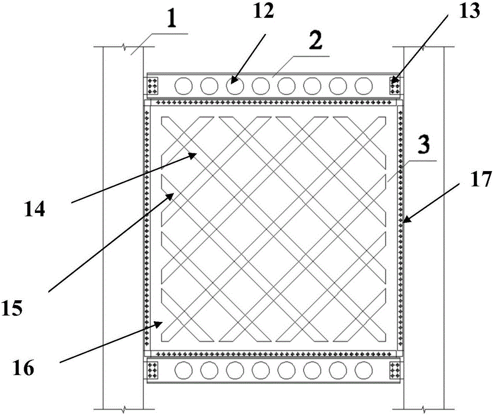
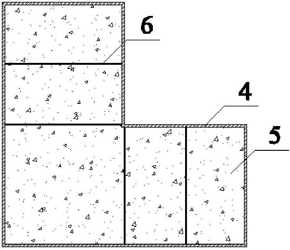
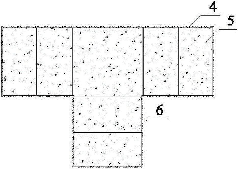
[0042] Such as figure 1 , Figure 5 As shown, the invention includes columns, steel beams and shear wall panels. The columns include pipe columns formed by welding peripheral steel plates, concrete filling layers and reinforcement bars. The pipe columns are filled with concrete to form concrete filling layers. The inner wall of the peripheral steel plate is provided with reinforcing ribs, the reinforcing ribs are tie bars, and the reinforcing ribs on the inner wall of the peripheral steel plate are arranged obliquely and intersecting.

[0043] Such as Figure 6 As shown, the top of the column and the two ends of the steel beam are connected by friction-type high-strength bolts, as shown in Figure 8-Figur...


PUM


Abstract

A prefabricated steel structure framework system comprises stand columns, a steel beam and a shear wall slab. Each stand column comprises a pipe column formed by welding peripheral steel plates, a concrete-filled layer and reinforcing ribs, wherein the pipe column is filled with concrete to form the concrete-filled layer, and the reinforcing ribs are arranged on the inner walls of the peripheral steel plates. The tops of the stand columns are connected with the two ends of the steel beam through friction type high-strength bolts, the cross section of the steel beam is in an H shape, the steel beam comprises an upper flange plate, a lower flange plate and a web for connecting the upper flange plate and the lower flange plate, the web is provided with holes, and a pipeline is arranged through the holes in the web. The shear wall slab is hinged to the outer sides of the peripheral steel plates of the pipe columns and provided with inclined long-strip holes. Hinging is adopted for framework beam-column joints, vertically-distributed force and horizontally-distributed force in the framework shear wall structure system are separated, stress is definite, the energy dissipation performance of the joints is improved, the deformation of the joints is improved, and too early fracture damage of the joints is avoided.

Description

technical field [0001] The invention relates to the technical field of steel structure frames, in particular to an assembled steel structure frame system. Background technique [0002] Compared with concrete structures, steel structure system components can be produced in a standardized manner, the construction period is short, the quality is easy to control, and the materials can be recycled. It is an excellent structural system. However, at present, most of the existing steel structure system node designs in China use rigid nodes, which bear complex forces and bear relatively large negative bending moments. Chinese Patent No. CN201410111074.2 discloses an invention patent titled "Industrialized Assembled Honeycomb Beam Steel Structure Eccentric Support System with Rigid Nodes"; Chinese Patent No. CN201210063584.8 discloses a titled "A Steel Structure Beam-Column Assembly Invention patent of "type rigid joint"; Chinese patent number CN201010123152.2 discloses an invention ...

Claims


Application Information

Patent Timeline
Patent Type & Authority Applications(China)
IPC IPC(8): E04B1/30E04B1/14E04C3/08E04B2/56E04B1/343
CPCE04B1/14E04B1/30E04B1/34321E04B2/56E04C3/083
Inventor 胡树青王培军张露露员建成马国润
Owner SHANDONG ZHONGTONG STEEL STRUCTURE ENG
Why Eureka
Try Eureka