
Pendulum type constant liquid level intelligent pumping unit and constant liquid level oil production method of the pumping unit

A technology of constant liquid level and pumping unit, which is applied in the fields of fluid production, earthwork drilling, wellbore/well components, etc., which can solve the problem of inability to directly display the power map, unstable position of the dynamic liquid level, and difficulty in adjusting the stroke order, etc. problems, to achieve the effect of automatic parameter adjustment to save, reduce labor time, and facilitate stroke adjustment.

Active Publication Date: 2018-05-25
DAQING HUALI MECHANICAL MFG
View PDF7 Cites 0 Cited by
  • Summary
  • Abstract
  • Description
  • Claims
  • Application Information

AI Technical Summary

Problems solved by technology

[0002] At present, the four-link beam pumping unit commonly used in oil fields has high power consumption, unstable fluid surface position, low system efficiency, and cannot directly display power diagrams. It is difficult to achieve load balance, low reversing efficiency, and large impact. , not easy to adjust stroke times

Method used


Image

  • Pendulum type constant liquid level intelligent pumping unit and constant liquid level oil production method of the pumping unit
  • Pendulum type constant liquid level intelligent pumping unit and constant liquid level oil production method of the pumping unit
  • Pendulum type constant liquid level intelligent pumping unit and constant liquid level oil production method of the pumping unit

Examples


Embodiment 1

[0026] A kind of pumping unit constant liquid surface oil recovery method of the present invention, realizes through following steps:

[0027] a. Determine the fluid level;

[0028] b. Collect the uplink and downlink active power of the motor;

[0029] c. Calculate the average uplink and downlink power;

[0030] d. Adjust stroke times: when the uplink power is greater than the average power of uplink and downlink, the dynamic liquid level will decrease and the stroke times will be reduced;

[0031] e. Constant liquid level oil recovery: adjust the stroke times of step d within the cycle time through the intelligent control device to achieve power balance and constant liquid level oil recovery.

Embodiment 2

[0033] A kind of pumping unit constant liquid surface oil production method of the present invention, realizes through following steps, as figure 1 Shown:

[0034] a. Determine the fluid level;

[0035] b. Collect the uplink and downlink active power of the motor;

[0036] c. Calculate the average uplink and downlink power;

[0037] d. Adjust stroke times: when the uplink power is greater than the average power of uplink and downlink, the dynamic liquid level will decrease and the stroke times will be reduced;

[0038] e. Constant liquid level oil recovery: adjust the stroke times of step d within the cycle time through the intelligent control device to achieve power balance and constant liquid level oil recovery.

[0039] The determination of the position of the dynamic fluid surface described in step a is realized by the following method: obtain the work W of the sucker rod weight 杆 , the work done by the weight of the oil column W 油 , the work done by the weight of the...

Embodiment 3

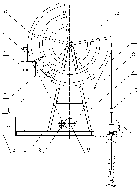
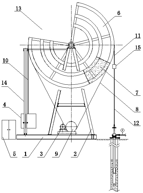
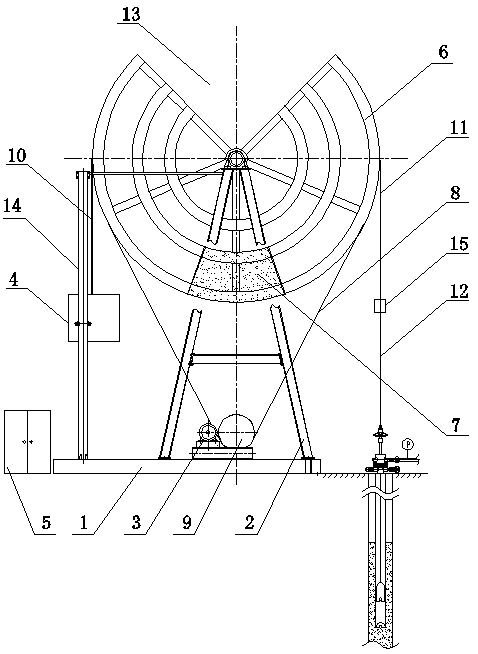
[0042] Pendulum type constant liquid level intelligent pumping unit of the present invention, as figure 1 As shown, it is composed of a base 1, a bracket 2, a motor 3, a counterweight 4 and an electrical control system 5. The bottom of the bracket 2 is fixed to the base 1, and a swing wheel 6 is installed on the top, and a pendulum is arranged at the bottom of the swing wheel 6. The counterweight 7 and the outer periphery of the oscillating wheel 6 are provided with a driving rope 8 and are connected in transmission with the driving wheel 9 fixed on the base 1, and the arc on one side of the top of the oscillating wheel 6 is fixedly connected with a counterweight lanyard 10. A sucker rod hanging rope 11 is fixedly connected to the arc on the other side, the bottom end of the counterweight hanging rope 10 is connected to the counterweight 4, and the bottom end of the sucking rod hanging rope 11 is connected to the sucker rod 12. The drive wheel 9 is connected to the motor 3 in ...


PUM


Abstract

The invention relates to a pendulum type constant-liquid-level intelligent pumping unit and a pumping unit constant-liquid-level oil extraction method and belongs to oil extraction devices. The pendulum type constant-liquid-level intelligent pumping unit is formed by a base, a support, a motor, a balancing weight and an electric control system, wherein the bottom of the support is fixed with the base, a swing wheel disc is arranged at the top of the support, a pendulum counterweight is arranged at the lower part of the swing wheel disc, a driving rope is arranged at the periphery of the swing wheel disc and is in driving connection with a driving wheel fixed on the base, a circular arc at one side of the top end of the swing wheel disc is fixedly connected with a counterweight sling, a circular arc at the other side of the top end of the swing wheel disc is fixedly connected with a sucker rod sling, the bottom end of the counterweight sling is connected with the balancing weight, and the bottom end of the sucker rod sling is connected with a sucker rod. The pendulum type constant-liquid-level intelligent pumping unit can save electric energy, eliminate a crank-link mechanism, save steel, realize constant-liquid-level oil extraction, realize monitoring on the position of a movable liquid level, display an indicator diagram in real time without an indicator, calculate liquid output, realize remote data transmission, improve pump efficiency, realize automatic parameter adjustment and save great manpower and material resources, and is small in reversing impact and easy for adjustment of stroke and stroke frequency.

Description

technical field [0001] The invention belongs to an oil production device and method, in particular to a pendulum type constant liquid level intelligent oil pumping unit and a constant liquid level oil production method for the pumping unit. Background technique [0002] At present, the four-link beam pumping unit commonly used in oil fields has high power consumption, unstable fluid surface position, low system efficiency, and cannot directly display power diagrams. It is difficult to achieve load balance, low reversing efficiency, and large impact. , It is not easy to adjust the stroke times. Contents of the invention [0003] The present invention aims at the deficiencies in the background technology, and proposes a pendulum type constant liquid level intelligent pumping unit and a constant liquid level oil recovery method for the pumping unit. [0004] A kind of pumping unit constant liquid surface oil recovery method of the present invention, realizes through followin...

Claims


Application Information

Patent Timeline
Patent Type & Authority Patents(China)
IPC IPC(8): E21B43/00
CPCE21B43/121E21B43/126
Inventor 袁东升张宇超刘东旭
Owner DAQING HUALI MECHANICAL MFG
Learn More