Balance valve

A technology of balancing valve and valve body, applied in the field of balancing valve, can solve the problems of energy loss, low efficiency, increased back pressure, etc., and achieve the effects of reducing energy loss, improving work efficiency, and having a simple and reasonable structure

Active Publication Date: 2016-09-21
宁波市镇海天地液压有限公司
View PDF6 Cites 11 Cited by
  • Summary
  • Abstract
  • Description
  • Claims
  • Application Information

AI Technical Summary

Problems solved by technology

Balance valves are usually used in conjunction with telescopic cylinders, but due to their unreasonable structural settings, traditional balance valves not only have poor overflow effects, but also when the piston rod of the telescopic cylinder retracts, the oil return from the rodless chamber is not smooth, making the back pressure Elevation and liquid resistance increase, resulting in serious energy loss and low efficiency

Method used


Image

  • Balance valve

Examples


Embodiment Construction

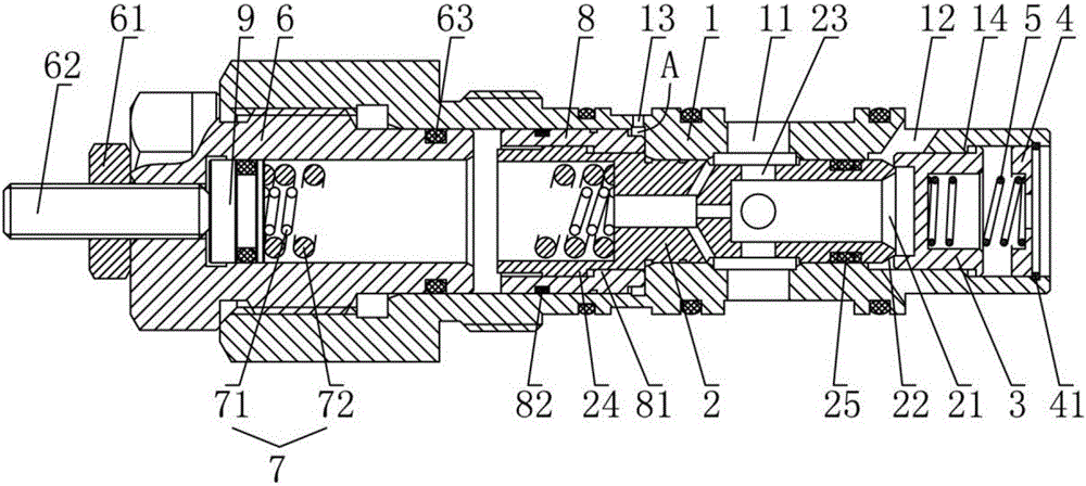
[0023] The present invention will be further described below in conjunction with the accompanying drawings.

[0024] Such as figure 1 The balance valve shown includes a valve body 1, a main valve core 2 and a one-way valve core 3 respectively arranged in the valve body 1, and the valve body 1 is respectively provided with a first oil port 11 and a second oil port 12 And the control oil port 13, the front end of the valve body 1 is provided with a spring seat 4, the inner wall of the valve body 1 is provided with a limit step 14 that cooperates with the stop of the one-way valve core 3, and the one-way valve core 3 is movable on the limit step Between 14 and the spring seat 4, and between the spring seat 4 and the one-way valve core 3, a one-way valve spring 5 is arranged.

[0025] The front end of the main valve core 2 is provided with a valve port 21 corresponding to the second oil port 12, and the outer wall of the valve port 21 is provided with an annular cone surface 22 t...


PUM


Abstract

The invention discloses a balance valve which comprises a valve body, a main valve element and a one-way valve element. The valve body is provided with a first oil port, a second oil port and a control oil port. A spring seat is arranged at the front end of the valve body. A one-way valve spring is arranged between the spring seat and the one-way valve element in an abutting manner. A valve port corresponding to the second oil port is formed in the front end of the main valve element. An annular conical face in sealing fit with the one-way valve element is arranged on the outer wall of the valve port. An oil passing hole corresponding to the first oil port is formed in the middle portion of the main valve element. The first oil port communicates with the valve port through the oil passing hole. A screw plug is arranged at the rear end of the valve body. A spring set is arranged between the rear end of the main valve element and the screw plug in an abutting manner. The position between the main valve element and the valve body is further sleeved with a guide sleeve corresponding to the control oil port. The guide sleeve and the main valve element are in axial linkage fit. A control oil cavity is formed between the guide sleeve and the valve body. The control oil port communicates with the control oil cavity. The balance valve is simple and reasonable in structure, good in overflowing effect and smooth in oil return, energy losses can be reduced easily, and the work efficiency is improved.

Description

technical field [0001] The invention relates to the technical field of valves, in particular to a balance valve. Background technique [0002] Balance valve, also known as load control valve or motion control valve, is a key hydraulic component in hydraulic load bearing system. The counterbalance valve is characterized by three valves in one: First, as a check valve, it allows unrestricted flow into a hydraulic actuator (such as a cylinder or motor) to lift a load, and then locks the circuit to maintain the load position The second is as a hydraulic control throttle valve, which controls the opening of the throttle valve through the control port, so as to control the speed and make the load drop smoothly according to the required speed; the third is as a relief valve, when there is no control pressure, but When the pressure at the load port (due to, for example, thermal expansion or external force) exceeds the set pressure, the relief valve opens to avoid damage to the hydr...

Claims


Application Information

Patent Timeline
Patent Type & Authority Applications(China)
IPC IPC(8): F15B13/02
CPCF15B13/029F15B2013/002
Inventor 林福明
Owner 宁波市镇海天地液压有限公司
Why Eureka
Try Eureka