Self-supporting car washing method and car washer
A self-service, car-washing technology, applied in vehicle exterior cleaning devices, instrument-controlled coin-operated equipment, and coin-operated equipment for distributing discrete items, etc., can solve problems such as time delay, discount on cleaning effects, and waste of water resources , to avoid losses, avoid cleaning dead corners, and achieve the effect of safety and convenience
- Summary
- Abstract
- Description
- Claims
- Application Information
AI Technical Summary
Problems solved by technology
Method used
Image

Examples
Embodiment Construction
[0040] The present invention will be further described in detail below in conjunction with the accompanying drawings and embodiments.
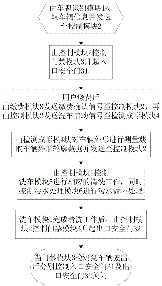
[0041] The invention provides a self-service car washing method, such as figure 1 shown, including the following steps:
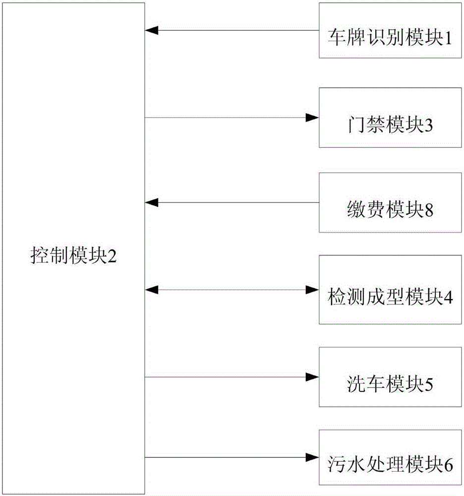
[0042] 1) The vehicle information is extracted by the license plate recognition module 1 and sent to the control module 2;
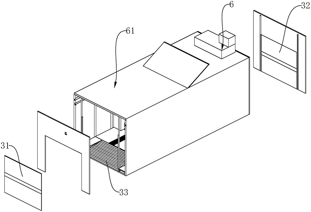
[0043] 2) The received vehicle information is identified by the control module 2, and when the identification result meets the set conditions, the control module 2 sends the first opening information to the access control module 3, and the access control module 3 controls the entrance security door 31 to automatically rise;
[0044] 3) After the customer pays in the payment module 8 through the mobile terminal, the payment confirmation signal is sent to the control module 2 by the payment module 8, and then the car washing start signal is sent to the detection and forming module 4 by the control modu...
PUM
 Abstract
Description
Claims
Application Information
PatSnap Eureka turns technology decisions into work you can execute. Powered by our Innovation Knowledge Graph, it runs expert workflows across engineering, life sciences, materials and intellectual property. Get your review-ready output in minutes.


