Unified energy control system

An energy control and controller technology, applied in AC networks to reduce harmonics/ripples, reactive power adjustment/elimination/compensation, multiphase network elimination/reduction of asymmetry, etc. The grid voltage rises, there is no large-capacity energy storage device, etc., to achieve the effect of improving safety and stability, suppressing high-order harmonic resonance, and good industrial application prospects

Active Publication Date: 2016-09-21
湖南华大紫光科技股份有限公司
View PDF4 Cites 21 Cited by
  • Summary
  • Abstract
  • Description
  • Claims
  • Application Information

AI Technical Summary

Problems solved by technology

At present, the regenerative braking energy of the electric locomotive is generally fed back directly to the grid, which will cause the voltage of the catenary to rise, and may cause the protection of the traction substation to malfunction and cause an impact on the grid
[0003] In addition, with the rapid development of electrified railways in my country, power quality problems such as negative sequence, reactive power, harmonics, and feeder voltage fluctuations and deviations caused by electrified railway load characteristics and traction transformer wiring types have become increasingly prominent. These problems not only affect The normal operation of the traction power supply system also brings hidden dangers to the safe and stable operation of the power grid
The methods to control high-order harmonics mainly include passive filtering and active filtering (APF). The cost of source filtering is high, and the loss of passive filtering is large. Therefore, there is still a lack of economical and effective treatment methods for high-order harmonic resonance problems in electrified railways.
The control of reactive power and feeder voltage fluctuations and deviations mainly uses dynamic var compensator (SVC) and static var generator (SVG). Solve the problem of feeder voltage fluctuation and deviation
The railway power conditioner (RPC) can comprehensively solve the negative sequence and reactive power problems, but it is difficult to efficiently solve the problem of regenerative braking energy utilization. Although RPC can transfer regenerative braking energy from one power supply arm to another power supply arm, due to Without a large-capacity energy storage device, if there is no traction load on the power supply arm that receives the energy, regenerative braking energy cannot be used efficiently, and in the end it can only be fed back to the grid, causing waste and impact, and it is difficult to meet the needs of railway users

Method used


Image

  • Unified energy control system
  • Unified energy control system
  • Unified energy control system

Examples


Embodiment 1

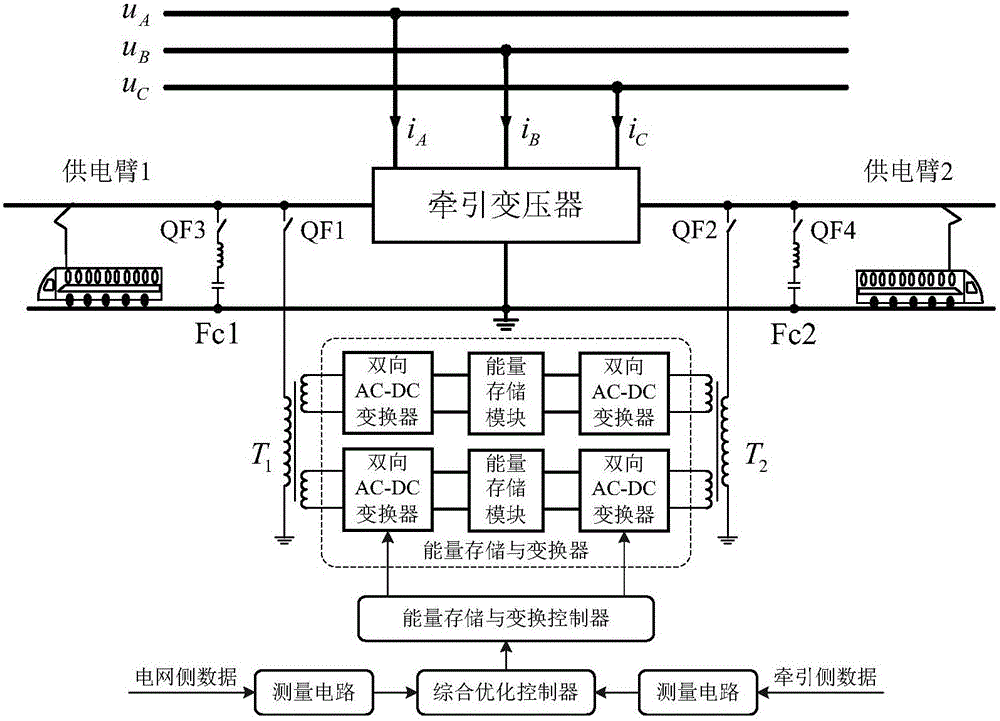
[0042] Example 1, such as figure 1 As shown, a unified energy control system according to an embodiment of the present invention includes:

[0043] The single-phase multi-winding isolation transformer is connected to the power supply arm of the traction transformer and performs isolation and step-down. The high-voltage sides of the two single-phase multi-winding isolation transformers T1 and T2 are respectively connected to the two power supply arms of the traction transformer through connection switches QF1 and QF2, and the low-voltage sides of T1 and T2 include at least one low-voltage winding.

[0044] The energy storage and converter is used to store the braking energy of the traction locomotive in real time, and control the release of the stored energy, realize the two-way flow of active power of the two power supply arms, and compensate the reactive power of the two power supply arms. The energy storage and converter includes two energy storage and conversion sub-module...

Embodiment 2

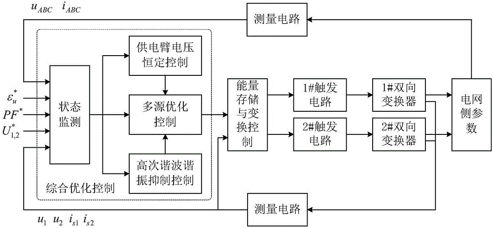
[0051] Example 2, such as figure 2 As shown, the present invention also provides a comprehensive optimization control method of a unified energy control system, the method comprising the following steps:

[0052] Step 1. At the beginning of each sampling period, measure the three-phase voltage u of the circuit on the grid side of the traction transformer ABC , three-phase current i ABC and the two-phase feeder voltage u on the traction side of the traction transformer 1 , u 2 and two-phase feeder current i s1 i s2 Carry out sampling respectively, and input the sampling data into the state monitoring module;

[0053] Step 2, the three-phase voltage unbalance given value ε * u , Power factor given value PF * and two-phase feeder voltage given value U * 1,2 The input state monitoring module adopts the fast Fourier algorithm and the instantaneous power algorithm to obtain the real-time data and operation status of the traction transformer grid side and the traction tran...


PUM


Abstract

The invention discloses a unified energy control system, and the system comprises a single-phase multi-winding isolation transformer which is connected to a power supply arm; an energy storage and conversion device which comprises at least one energy storage and conversion submodule, wherein the input side of the energy storage and conversion submodule is connected with an auxiliary side winding, and the energy storage and conversion submodule comprises an energy storage module and a bidirectional AC-DC converter; a measurement circuit which is connected with a power grid side and a traction side; a comprehensive optimization controller which is connected with the measurement circuit; and an energy storage and conversion controller which is connected with the comprehensive optimization controller and the bidirectional AC-DC converter. The invention also provides a comprehensive optimization control method for the unified energy control system. The beneficial effects of the invention are that the system achieves the real-time storage and release of regenerative braking energy of a traction engine, and efficiently uses the regenerative braking energy; the system carries out electricity storage when there is no traction load, preferably carries out charging for energy storage during valley and discharging for energy supply during peak, achieves the peak cutting and valley filling and demand-side response management, improves the power supply capability and reduces the operation cost; the system achieves the treatment of the fluctuation and deviation of negative sequence, reactive power, harmonic wave and voltage.

Description

technical field [0001] The invention relates to the technical field of electrified railways, in particular to a unified energy control system. Background technique [0002] At present, my country's electric locomotives generally adopt two braking methods: energy consumption braking and regenerative braking. Energy-consumption braking is mainly used for AC and DC locomotives, and regenerative braking is mainly used for AC and DC locomotives. With the development of high-speed and heavy-duty electrified railways in my country, AC-DC locomotives have become the main development direction. Due to the high power of regenerative braking, how to deal with regenerative braking energy has become a problem that cannot be ignored. At present, the regenerative braking energy of electric locomotives is usually directly fed back to the grid, which will cause the voltage of the catenary to rise, and may cause the protection of the traction substation to malfunction and cause an impact on...

Claims


Application Information

Patent Timeline
Patent Type & Authority Applications(China)
IPC IPC(8): H02J3/32H02J3/01H02J3/18H02J3/26H02J3/12
CPCH02J3/01H02J3/12H02J3/1821H02J3/26H02J3/32Y02E40/30Y02E40/40Y02E40/50
Inventor 罗隆福周冠东陈跃辉罗培严文交张志文马芳
Owner 湖南华大紫光科技股份有限公司
Why Eureka
Try Eureka