A continuous automatic drying and curing device

A curing device and automatic technology, which is applied to the device, coating, pretreatment surface, etc. for applying liquid to the surface, can solve the difficulty in achieving tightness at the inlet and outlet, and reduce the utilization rate of the interior space of the curing room. , low work efficiency and other problems, to achieve the effect of compact and reasonable overall structure, easy replacement and less space occupation

Active Publication Date: 2019-05-07
ZHEJIANG DOULAN INTELLIGENT EQUIP CO LTD
View PDF5 Cites 0 Cited by
  • Summary
  • Abstract
  • Description
  • Claims
  • Application Information

AI Technical Summary

Problems solved by technology

[0005] Although the above technical solution realizes the automation of the solar cell module production line by setting the curing conveying line through the curing room, there are still some deficiencies. Lines enter the curing room synchronously, which requires that the curing conveying line run through the entire curing room and ensure that the structure and performance requirements of the entire curing conveying line are consistent, the cost is high, and the sealing at the inlet and outlet is difficult to achieve , the heat loss is large; in addition, in this technical solution, the curing conveyor line is at least two flat-top conveyor chains arranged in parallel. Since the flat-top conveyor chains are prone to slack during use, it adopts the method of setting the chain below the flat-top conveyor chains. Plate support device to increase the stability of transmission, but the structure is complicated, which reduces the utilization rate of the internal space of the curing room and low work efficiency

Method used


Image

  • A continuous automatic drying and curing device
  • A continuous automatic drying and curing device
  • A continuous automatic drying and curing device

Examples


Embodiment 1

[0033] Embodiments are described below with reference to the drawings. In addition, the examples shown below do not limit the content of the invention described in the claims in any way. In addition, all the contents of the configurations shown in the following embodiments are not limited to be essential to the solution of the invention described in the claims.

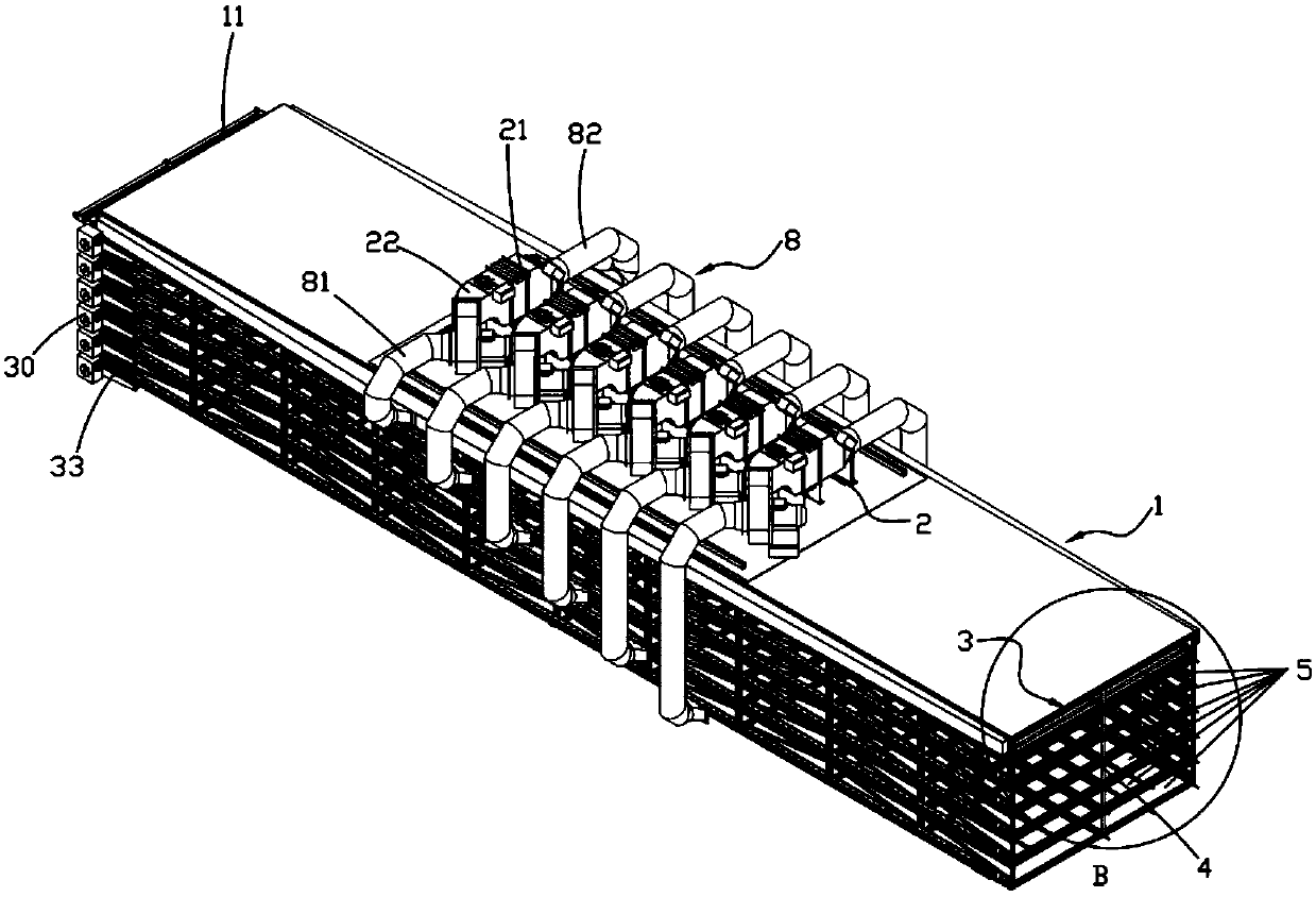
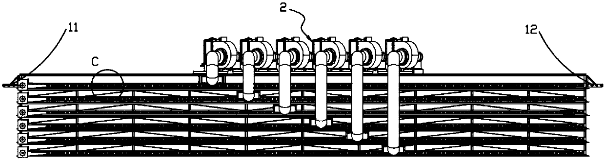
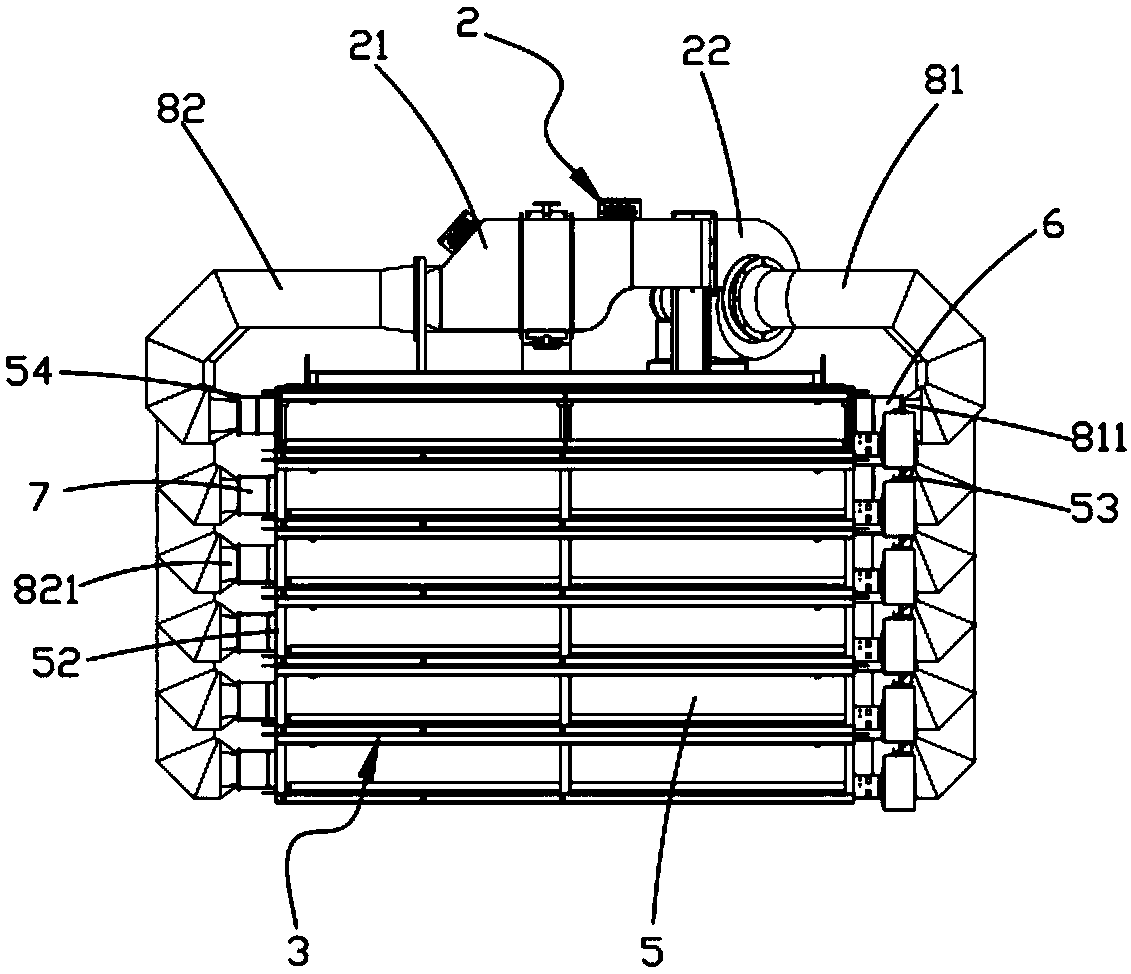
[0034] Such as figure 1 As shown, a continuous automatic drying and curing device includes a curing room 1 with heat insulation function and a heat exchange system 2 arranged above the curing room 1, and a temperature control device is also arranged in the curing room 1 , a humidity control device and an exhaust device, the heat exchange system 2 includes a humidification heater 21 and an exhaust unit 22 for sending heated air and water vapor into the curing room 1; the interior of the curing room 1 is set At least two groups of horizontal conveying units 3 arranged in layers from top to bottom, each layer of convey...


PUM


Abstract

The invention relates to a continuous automatic drying solidification device. The continuous automatic drying solidification device comprises a solidification room and heat exchange systems. Each heat exchange system comprises a humidification heater and an air draft unit. At least two sets of horizontal conveying units arranged in a layered mode from top to bottom are arranged in the solidification room. A partition plate is fixedly arranged at the bottom of each layer of conveying unit. Independent solidification chambers are formed by closed spaces between the partition plate on the first layer and the top of the solidification room, between two adjacent partition plates and between the partition plate on the tail layer and the bottom of the solidification chamber. An air inflow channel and an air outlet channel communicated with each solidification chamber are formed between a first outer shield plate and a second outer shield plate and the two side walls of the solidification chamber, wherein the first outer shield plate and the second outer shield plate are arranged on the outer portions of the two side walls of the solidification chamber respectively. Each solidification chamber is provided with one independent heat exchange system. A flow guide mechanism is arranged in each air inflow channel. The independent solidification chambers are formed in the solidification room, different products can be operated at the same time, the product placement intensity is high, the heat utilization rate is high, and temperature and humidity fields in the solidification chambers are stable.

Description

technical field [0001] The invention belongs to the technical field of battery processing equipment, and in particular relates to a continuous automatic drying and curing device, which is mainly used for automatic drying and curing of battery plate boxes. Background technique [0002] In the production process of batteries, the curing of the plates is an extremely important process in the manufacture of batteries. After the grids are filled with lead paste, through the curing process, the particles of the lead paste are connected to each other to form a continuous and solid skeleton, and are tightly attached. On the grid, the solidification of the plate directly affects the electrical performance of the battery. [0003] At present, the curing of the polar plates is placed in a closed drying room, and the plates are stacked in the drying room through the carrier, and the humidity and humidity in the drying room are adjusted through the circulation system for generating water...

Claims


Application Information

Patent Timeline
Patent Type & Authority Patents(China)
IPC IPC(8): B05D3/04H01M4/21
CPCB05D3/0473H01M4/21Y02E60/10
Inventor 钱顺荣梁电法俊卿钱梦飞
Owner ZHEJIANG DOULAN INTELLIGENT EQUIP CO LTD
Why Eureka
Try Eureka