Heat transfer film cutting device with function of freely regulating cutters

A thermal transfer film and cutting technology, applied in metal processing and other directions, can solve the problems of inability to relatively adjust the spacing and angle, time-consuming and laborious disassembly and replacement, affecting production efficiency, etc., to improve market competitiveness, increase work cooperation, improve The effect of production efficiency

Inactive Publication Date: 2016-09-28
苏州锦安新材料科技有限公司
View PDF8 Cites 11 Cited by
  • Summary
  • Abstract
  • Description
  • Claims
  • Application Information

AI Technical Summary

Problems solved by technology

[0005]Of course, the above-mentioned mechanism has greatly improved the production efficiency, and the positioning accuracy has been greatly improved compared with manual work. However, in long-term practice, we still find the following problems: due to The cutter around the thermal transfer film in this type of equipment is fixed, and the spacing and angle cannot be adjusted relatively, so it can only be cut to produce a thermal transfer film of a fixed shape (usually rectangular) and size
However, the specific requirements of the market for thermal transfer film are complex and changeable. Obviously, a product with a fixed shape and size cannot well meet the market demand and bring higher benefits to the enterprise.
In order to change the size and shape, the current practice of enterprises is relatively single and clumsy, that is, to disassemble and replace the whole ring cutter
For the cutting of a batch of products, it is necessary to re-open the mold to process and produce the corresponding cutter. For the enterprise, not only the disassembly and replacement is time-consuming and laborious, but also affects the production efficiency, and the production cost is also greatly increased.

Method used


Image

  • Heat transfer film cutting device with function of freely regulating cutters

Examples


Embodiment

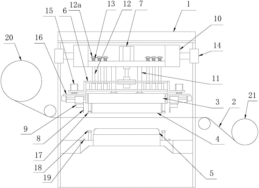
[0025] Example: as shown in the figure 1 Shown is a specific embodiment of a thermal transfer film cutting device with a cutter free adjustment function of the present invention, which has a bracket 1 , Set on the bracket through the lifting drive mechanism 1 The positioning and cutting mechanism of the thermal transfer film on the upper surface, the substrate positioning mechanism arranged under the positioning and cutting mechanism of the thermal transfer film, and the positioning mechanism for the thermal transfer film 2 The reel mechanism conveyed through the middle of the cutting mechanism and the positioning mechanism. The reel mechanism described in the present embodiment has unwinding roller as conventional technology 20 and winding roller 21 ,by PLC The controller (not shown in the figure) controls the thermal transfer film 2 delivery. The lifting drive mechanism is a lifting cylinder (not shown in the figure), and the lifting cylinder is cont...


PUM


Abstract

The invention discloses a heat transfer film cutting device with a function of freely regulating cutters. The heat transfer film cutting device is improved on the basis of a normal cutter drive mechanism, and a plurality of cutter controllable regulating units are designed at the periphery of a cutter mounting frame driven and controlled by a cutter stamping drive air cylinder for replacing an original inflexible cutter mounting mechanism. Each cutter controllable regulating unit comprises a clamping block for fixing one cutter and perpendicular to the cutter, a transverse displacement servo drive device connected with and used for driving the clamping block to transversely move, and a horizontal rotary angle servo drive device connected with and used for driving the transverse displacement servo drive mechanism to rotate, and further comprises a PLC which is used for controlling the transverse displacement servo drive mechanism and the horizontal rotary angle servo drive device to act. By virtue of the cutter controllable regulating units, degree of freedom, in aspects of transverse movement and rotation, of the cutters are realized, so that spacing and angles of the cutters can be freely regulated within a certain range, and therefore, cutting shapes and dimensions of a heat transfer film are increased to adapt to needs, and production cost of enterprises is saved while production efficiency is improved.

Description

technical field [0001] The invention belongs to the technical field of thermal transfer film production equipment, and in particular relates to a thermal transfer film cutting device with the function of free adjustment of a cutter. Background technique [0002] Thermal transfer production usually refers to the process of cutting the prepared thermal transfer film and laminating it on the substrate. The industry was originally operated manually, but the disadvantages are obvious, such as low efficiency and poor precision. In addition, there are situations where multiple films are stacked and difficult to separate and transferred together, resulting in serious waste of materials. For this reason, through continuous research and development in the industry, production equipment with a high degree of automation has been designed. [0003] A type of automatic equipment for thermal transfer film cutting and pad printing widely used in the industry at present, its structure is us...

Claims


Application Information

Patent Timeline
Patent Type & Authority Applications(China)
IPC IPC(8): B26D1/08B26D7/26
CPCB26D1/085B26D7/2628
Inventor 张福州芦俊
Owner 苏州锦安新材料科技有限公司
Why Eureka
Try Eureka