Improved locking device for main rotating shaft and application

A technology of locking device and main rotating shaft, applied in the field of locking devices, can solve problems such as slow lifting, damage to transported objects, etc.

Active Publication Date: 2016-09-28
施耐德电气(厦门)开关设备有限公司
View PDF11 Cites 7 Cited by
  • Summary
  • Abstract
  • Description
  • Claims
  • Application Information

AI Technical Summary

Problems solved by technology

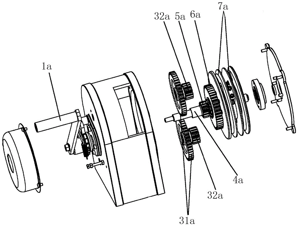
[0002] The circuit breaker of the existing switch cabinet generally solves the problem of the circuit breaker entering and exiting the switch cabinet through a lifting transfer vehicle (lifting handcart). Refer to the published patent document CN 201694790U, which discloses a lifting transfer vehicle with a reduction gear mechanism, such as figure 1 As shown, by manually turning the hand crank 1a of the lifting mechanism, the hand crank 1a will drive the main shaft 4a to rotate, thereby driving the main shaft 4a to drive the pinion 5a to rotate; through the pinion 5a and the large tooth of the double gear 3a 31a, the small tooth 32a of the double gear 3a meshes with the large gear 6a to achieve a two-stage deceleration, and the large gear 6a drives the wire wheel 7a to rotate, thereby driving the wire rope wound on the wire wheel 7a to go up and down, thereby pulling the guide rail. Slow lifting or lowering solves the safety problem of transferring the circuit breaker outside the cabinet, but with this solution, when transferring the circuit breaker or other objects, the human hand cannot leave the hand handle 1a, otherwise the object will fall by itself due to its own weight , causing damage to the transshipment object

Method used


Image

  • Improved locking device for main rotating shaft and application
  • Improved locking device for main rotating shaft and application
  • Improved locking device for main rotating shaft and application

Examples


Embodiment Construction

[0031] Taking the specific application of the main shaft locking device in the driving device of the lifting handcart as an example, the present invention will be described in detail in conjunction with the accompanying drawings.

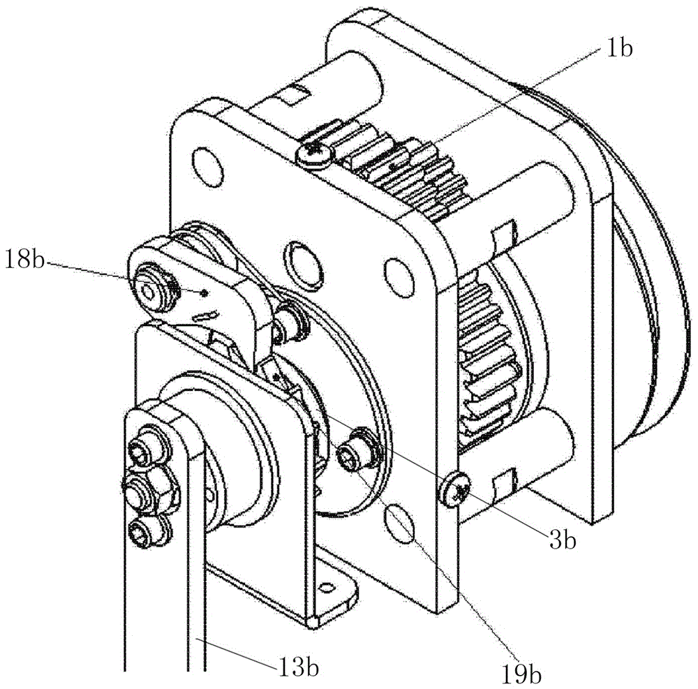
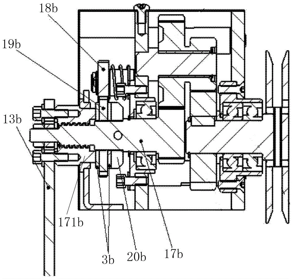
[0032] like image 3 , 4 , 5-1, 5-2 shown, a kind of improved lifting handcart power driving device, it comprises reduction gear box 1 and handle 2, and described reduction gear box 1 comprises chassis 10, reduction gear set, main shaft 11. External ratchet 12, ratchet 13, anti-rotation disk 14, first brake pad 15, second brake pad 16, connecting nut 17 and wire wheel 100; The large teeth on the main rotating shaft 11 are meshed with the small teeth to form (see figure 1 ), to achieve the purpose of deceleration; or as shown in Figures 5 and 6, a gear 111 is provided on the main shaft 11, the gear 111 meshes with the secondary reduction gear 112, and the small tooth end of the secondary reduction gear 112 is then connected to the The output gears...


PUM


Abstract

The invention discloses an improved locking device for a main rotating shaft. The device is characterized in that a torsional spring which can overcome screwing frictional resistance between the main rotating shaft and a connecting nut is additionally arranged between the connecting nut and the main rotating shaft so as to prevent the main rotating shaft from uncontrollable high-speed rotating caused by human errors; the connecting nut can overcome the thread frictional force relative to the main rotating shaft under the effect of the inverted torsion of the torsional spring, and thus the connecting nut can be rotated relative to the main rotating shaft, and as a result, the main rotating shaft can be braked. The invention also provides another scheme for locking the main rotating shaft. The scheme is characterized in that an inner pawl which can be limited through an elastic connector is arranged on a flywheel disc; in case that the main rotating shaft is subjected to uncontrollable high-speed rotating, the outward centrifugal force of the inner pawl on the flywheel disc can be utilized to overcome the tensioning force of the elastic connector, thus the inner pawl can be locked to an inner ratchet wheel, and as a result, the function of locking the main rotating shaft can be further achieved.

Description

technical field [0001] The invention relates to a locking device, in particular to a locking device for a main rotating shaft. Background technique [0002] The circuit breaker of the existing switch cabinet generally solves the problem of the circuit breaker entering and exiting the switch cabinet through a lifting transfer vehicle (lifting handcart). Refer to the published patent document CN 201694790U, which discloses a lifting transfer vehicle with a reduction gear mechanism, such as figure 1 As shown, by manually turning the hand crank 1a of the lifting mechanism, the hand crank 1a will drive the main shaft 4a to rotate, thereby driving the main shaft 4a to drive the pinion 5a to rotate; through the pinion 5a and the large tooth of the double gear 3a 31a, the small tooth 32a of the double gear 3a meshes with the large gear 6a to achieve a two-stage deceleration, and the large gear 6a drives the wire wheel 7a to rotate, thereby driving the wire rope wound on the wire whe...

Claims


Application Information

Patent Timeline
Patent Type & Authority Applications(China)
IPC IPC(8): F16H63/34B66D5/06
CPCB66D5/06F16H63/3425
Inventor 何国平毕珊明晓中王荣陈医平何平
Owner 施耐德电气(厦门)开关设备有限公司
Why Eureka
Try Eureka