Method and device for testing equipment antenna

A technology for testing equipment and equipment under test, applied in directions such as antenna radiation patterns, which can solve the problems of low efficiency, increased testing costs, and high testing costs

Inactive Publication Date: 2016-09-28
GUANGZHOU SHIYUAN ELECTRONICS CO LTD
View PDF6 Cites 26 Cited by
  • Summary
  • Abstract
  • Description
  • Claims
  • Application Information

AI Technical Summary

Problems solved by technology

[0003] However, this coupling test method has the following limitations: 1. It is necessary to configure an expensive comprehensive tester, and the test cost is high; and when the whole machine has multiple antennas, each antenna of the whole machine needs to be placed in different stations Separate testing further increases the cost of testing; on the other hand, a single station can only test one device at a time, and the efficiency is low

Method used


Image

  • Method and device for testing equipment antenna
  • Method and device for testing equipment antenna
  • Method and device for testing equipment antenna

Examples


Embodiment Construction

[0024] In order to make the object, technical solution and advantages of the present invention clearer, the present invention will be further described in detail below in conjunction with the accompanying drawings and embodiments. It should be understood that the specific embodiments described here are only used to explain the present invention, not to limit the present invention.

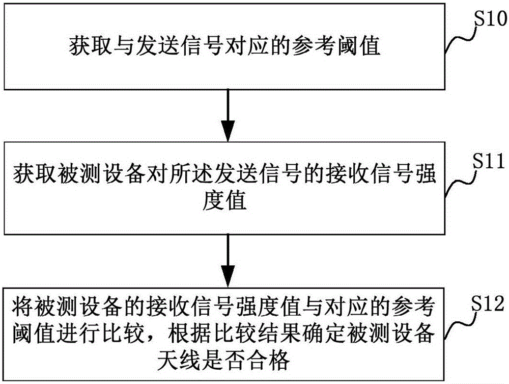
[0025] figure 2 It is a schematic flowchart of a method for testing an antenna of a device according to an embodiment; in this embodiment, it is described by taking the method applied to a test host as an example, and the test host may be a PC.

[0026] Such as figure 2 As shown, the method for testing a device antenna in this embodiment includes steps:

[0027] S10. Acquire a reference threshold corresponding to the sent signal.

[0028] In the embodiment of the present invention, the method of determining the reference threshold corresponding to the transmitted signal includes: obtaining the...


PUM


Abstract

The invention relates to a method and a device for testing an equipment antenna. The method comprises steps that received signal strength indication of tested equipment for a sending signal is acquired, and a reference threshold corresponding to the sending signal is acquired; the received signal strength indication of the tested equipment is compared with the corresponding reference value, whether the test equipment antenna is qualified is determined according to a comparison result; the reference threshold acquisition method comprises steps that received signal strength indication of reference equipment for a sending signal is acquired, and a reference threshold corresponding to the sending signal is determined according to the received signal strength indication of the reference equipment. The method is advantaged in that a test result is accurate, test cost can be saved, and test efficiency is improved.

Description

technical field [0001] The invention relates to the technical field of equipment testing, in particular to a method and a device for testing equipment antennas. Background technique [0002] As wireless devices become more and more popular, the quality requirements for antennas of wireless devices are also getting higher and higher. Defects caused by the welding and assembly of the antenna will affect the overall wireless performance of the whole machine. The main test method currently adopted for the inspection of antenna welding and assembly of wireless devices during factory production is coupling test, such as figure 1 , connect the coupling test fixture with the comprehensive tester, fix the device under test on the fixture, test the maximum power of the device under test, and compare the test data with the set standard value, so as to judge whether the antenna welding or assembly is good . [0003] However, this coupling test method has the following limitations: 1....

Claims


Application Information

Patent Timeline
Patent Type & Authority Applications(China)
IPC IPC(8): G01R29/10
CPCG01R29/10
Inventor 徐章龙
Owner GUANGZHOU SHIYUAN ELECTRONICS CO LTD
Why Eureka
Try Eureka