
A linear motor permanent magnet brake

A technology of linear motors and brakes, which is applied to permanent magnet clutches/brakes, electric components, electromechanical devices, etc., can solve problems such as non-linear locking, long braking time, and low mechanical reliability, and achieves simple operation and easy processing Simple, compact effect

Active Publication Date: 2019-07-26
KEDE NUMERICAL CONTROL CO LTD
View PDF1 Cites 0 Cited by
  • Summary
  • Abstract
  • Description
  • Claims
  • Application Information

AI Technical Summary

Problems solved by technology

[0003] The problem is that due to the spring structure, the braking time is long, the mechanical reliability is low, and it cannot be locked in a straight line

Method used


Image

  • A linear motor permanent magnet brake
  • A linear motor permanent magnet brake
  • A linear motor permanent magnet brake

Examples


Embodiment Construction

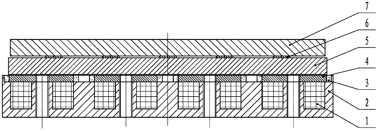
[0021] Such as figure 1 and 2 As shown, the linear motor brake of the present invention is mainly divided into two parts, which are respectively a static iron core assembly and a moving plate assembly. The static iron core assembly includes a coil 1, a static iron core 2, a yoke 4 and a magnetic steel 3; Plate 5, fixed plate 7 and leaf spring 6. The static iron core component is fixed to the secondary of the linear motor, and the moving plate component is fixed to the primary of the linear motor. After the brake is powered off, the coil cannot generate a magnetic field, and the magnetic steel magnetic field circuit indirectly connects the primary and secondary of the linear motor through the suction of the moving plate, that is, the motor is in the brake state and cannot run. After the brake is powered on, the coil generates a magnetic field, and the coil magnetic field circuit short-circuits the magnetic steel magnetic field circuit, and the magnetic steel magnetic field ci...


PUM


Abstract

The invention discloses a linear motor permanent magnetic brake. The linear motor permanent magnetic brake comprises a static iron core assembly and a moving plate assembly, wherein the static iron core assembly comprises multiple coils embedded in the static iron core; the upper portion of each coil is provided with a magnet yoke and magnet steel; the moving plate assembly comprises a fixed plate and a movable plate which are spaced by a spring sheet; and the fixed plate is placed above the magnet yokes and the magnetic steel. The linear motor permanent magnetic brake has the following advantages: 1, linear internal contracting brake is realized, the volume is small, and the weight is light; 2, the processing is simple, and the installation and maintenance are simple; 3, the connection is reliable, the brake is flexible, automatic control and long-distance operation of a work mechanism can be realized, and the brake time is extremely short; 4, the control power is small, and the service life is long; 5, the performance is stable, and the safety and reliability are high; 6, the structure is simple and compact, the operation is simple, and accurate combination can be guaranteed in quite short time; 7, diversified combination and application can be realized through adjusting features of the coils and the magnetic steel; and 8, the linear electromagnetic brake does not need motion at all, apart from an electromagnet, a brake using a permanent magnet does not need electric power, and thus the space and the efficiency can be reduced.

Description

technical field [0001] The invention relates to the fields of high-grade numerical control machine tools, production lines and the like, and more specifically relates to a brake. Background technique [0002] Chinese patent CN201320596839.7 is a brake device for a linear motor, which relates to a brake device for a linear motor. An annular static iron core with a coil on the outside of the sub-axis and an inner ring, the moving iron core is arranged between the inner ring of the static iron core and the mover shaft of the linear motor; a number of return springs matching the number of moving iron cores, and the return springs are installed on the static iron core . [0003] The problem is that due to the spring structure, the braking time is long, the mechanical reliability is low, and it cannot be locked in a straight line. Contents of the invention [0004] The invention provides a convenient and applicable brake. [0005] In order to achieve the above object, a linea...

Claims


Application Information

Patent Timeline
Patent Type & Authority Patents(China)
IPC IPC(8): H02K49/10H02K7/10
CPCH02K7/10H02K49/10
Inventor 姜贺王雪杨金明何毅迟宁李东明于勇郐娟
Owner KEDE NUMERICAL CONTROL CO LTD
Learn More