Hub electric system, electromobile and driving, braking and stroke-increasing method thereof

A technology for electric vehicles and hubs, applied in electric vehicles, control drives, vehicle energy storage, etc., can solve problems such as failure to achieve expected success, low cost performance, and low practical power consumption indicators

Inactive Publication Date: 2016-10-05
刘粤荣
View PDF8 Cites 1 Cited by
  • Summary
  • Abstract
  • Description
  • Claims
  • Application Information

AI Technical Summary

Problems solved by technology

[0004] In the electric vehicle market, in recent years, counterparts at home and abroad have tried to develop electric wheels with electric mechanisms installed on the rim, but they have not achieved the expected success. For electric bicycles, the shaft output power of the motor is transmitted through gears. Due to the use of traditionally designed motors and conventional power supply methods, its power conversion efficiency is similar to that of hub-type motors, and setting the motor on the outer edge of the rim will be limited by power
In the electric four-wheel vehicle market, the current mainstream idea of ​​developing high-power wheel-hub motors is to install the motor inside the wheel hub. Because the weight/volume ratio of conventional motors is low, the weight of the wheel hub increases greatly, and the practical power consumption index is not high. Low, and the cost performance is not high, and there are fewer types of products in the market
[0005] Short mileage is the weakness of electric vehicles at this stage. The industry generally believes that before high-energy batteries enter commercial use, it is unrealistic to increase the mileage of electric vehicles by increasing the number of batterie...

Method used


Image

  • Hub electric system, electromobile and driving, braking and stroke-increasing method thereof
  • Hub electric system, electromobile and driving, braking and stroke-increasing method thereof
  • Hub electric system, electromobile and driving, braking and stroke-increasing method thereof

Examples


Embodiment 1

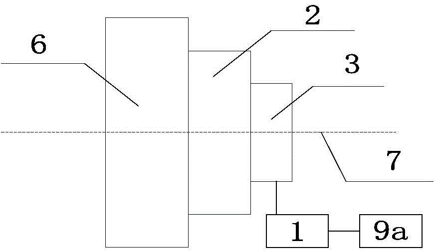
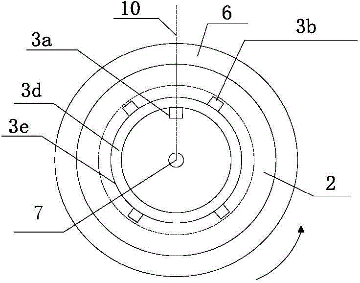
[0096] A wheel hub electric system of an electric vehicle and its matching electric two-wheeled vehicle are selected such as Figure 10a Shown vehicle frame 4, the circumference of wheel 5 is 1000mm, and battery pack 8b selects 24V12Ah lithium iron phosphate battery to be installed in the inside of vehicle frame; Electric device is located at the rear wheel of vehicle. The coaxial rotating body 3e of the electric device is a ring-shaped titanium-aluminum alloy ring with a rotating shaft and a circumference of 300mm. The outer edge of the alloy ring is fixedly connected with 8 rotor units 3b, and the inner part of the alloy ring is fixedly connected with the fixed shaft. On the device, a stator unit 3a is installed; the coaxial rotating body 3e is coaxially installed with the hub 6, and a deceleration / torque conversion device 2 composed of several gears is arranged in between, and the deceleration / torque conversion device 2 is used to realize the connection with the hub 6 Mecha...

Embodiment 2

[0104] The initial start-up current of embodiment 1 is changed to: power modulator in 5s with I 1 The intensity is 8A as the benchmark, corresponding to the rotation cycle of the coaxial body, the current intensity is automatically increased by 1.5% every next cycle, and the next work instruction of the drive control device 9a is waited for from the 6th second: if there is no input command from the drive control device, power modulation If the command given by the driving control device is to accelerate, the power modulator will execute T 1 with (T 2 +T 0) current sequence with a ratio of 1:5, and the average strength of real-time energization is given by the drive control device.

[0105] Others are the same as in Embodiment 1, and the slow acceleration mode is more suitable for safety design requirements. The moment when the aforementioned stator unit winding starts to be energized can also be changed to (T 1 +T 2 ) time period is a delay of 1% to 5% of the reference va...

Embodiment 3

[0107] An electromagnetic braking function is added to the electric device described in Embodiment 1.

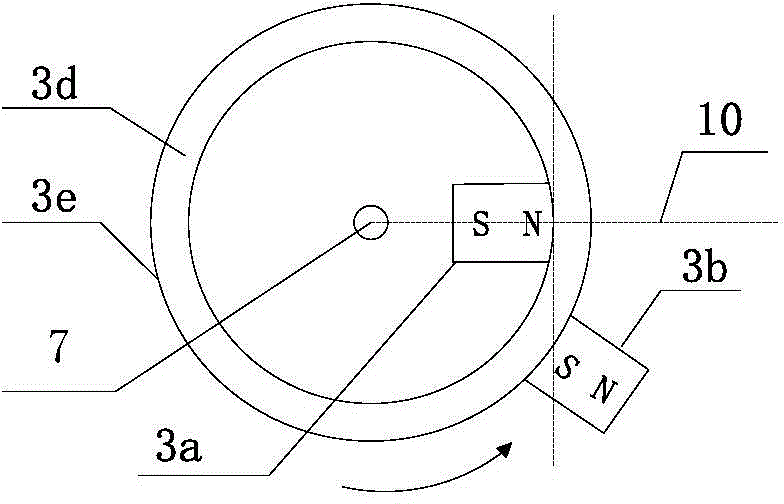
[0108] The electromagnetic braking device is a ten-level rheostat, and the power supply modulator correspondingly adds a braking signal input terminal 1e to electrically connect the electromagnetic braking device 9b, such as Figure 5c Shown; when the manual control electromagnetic brake device sends a braking signal, the power modulator cuts off T 1 corresponding to the timing current, start T 2 The time domain is energized, and the energization time domain is set so that the sensing unit 3c senses the rotor unit 3b around the shaft to from (about 5 degrees) position to The time period for the 0 position.

[0109] The brake current output by the power modulator corresponds to the ten-level resistance setting of the electromagnetic braking device 9b as ten-level intensity, and the set output current intensity is: the first level is 6A, the last level is 11A, and the t...


PUM


Abstract

The invention discloses a hub electric system and an electromobile. The hub electric system comprises a hub, a speed reducing/torque changing device, a power source modulator, a driving operation and control device and at least an electric device, each electric device comprises a coaxial swivel, at least one stator unit and at least one permanent magnet rotor unit, the rotor units are arranged on the corresponding swivels, and relative air gaps between the stator units and the rotor units are not greater than 60 mm; the coaxial swivels and the hub are arranged coaxially, electromagnetic poles of the stator units are opposite to magnetic poles, which move to face the stator units, of the rotor units, the power source modulator acquires a user' instruction through the driving operation and control device/an electromagnetic braking device and correspondingly outputs time sequence current to drive/brake the hub electric system. The electromobile comprises a frame, a battery pack and at least one wheel. At least one hub electric system is arranged, and a stroke increasing system supplements power for a secondary battery pack when in a set logic state.

Description

technical field [0001] The invention relates to the field of electric vehicle and its power source power design, in particular to a structure of an in-wheel electric system, a driving and braking method thereof, and a range-extending method of an electric vehicle including the in-wheel electric system. Background technique [0002] At present, electric vehicles on the market are mainly two-wheeled vehicles. The market share of electric two-wheeled vehicles in my country has reached more than 150 million; in addition to two-wheeled vehicles, electric tricycles have also risen rapidly in recent years. According to industry information, in 2013, the number exceeded 10 million. The low-speed electric four-wheel vehicle market for regional use has also achieved considerable development. [0003] At present, electric vehicle motors are developing from general-purpose to professional design, and their power controllers are also trying to use pulse modulation technology to reduce the...

Claims


Application Information

Patent Timeline
IPC IPC(8): B60K7/00B60L11/18B60L15/00
CPCY02T10/70
Inventor 刘粤荣陈方
Owner 刘粤荣
Why Eureka
Try Eureka