Downhole vibration monitoring method

A vibration monitoring and stick-slip vibration technology, applied in the automatic control system of drilling, drilling equipment, earth-moving drilling, etc., can solve the problems of insufficient wellbore purification, low rock breaking efficiency, poor mud performance, etc.

Active Publication Date: 2016-10-05
BC P INC CHINA NAT PETROLEUM CORP +2
View PDF7 Cites 12 Cited by
  • Summary
  • Abstract
  • Description
  • Claims
  • Application Information

AI Technical Summary

Problems solved by technology

[0004] During the process of drilling, the identification of the vibration intensity of the drilling tool lacks effective means of visualization and quantitative judgment. When the ROP is low, the well team technicians often blame the formation strength increase, drill bit wear, insufficient wellbore purification, poor mud performance, etc. factors, ignoring the bottleneck factor of low rock breaking efficiency caused by drilling tool vibration

Method used


Image

  • Downhole vibration monitoring method
  • Downhole vibration monitoring method
  • Downhole vibration monitoring method

Examples


Embodiment Construction

[0111] In order to make the purpose, technical solutions and advantages of the embodiments of the present invention more clear, the embodiments of the present invention will be further described in detail below in conjunction with the accompanying drawings. Here, the exemplary embodiments and descriptions of the present invention are used to explain the present invention, but not to limit the present invention.

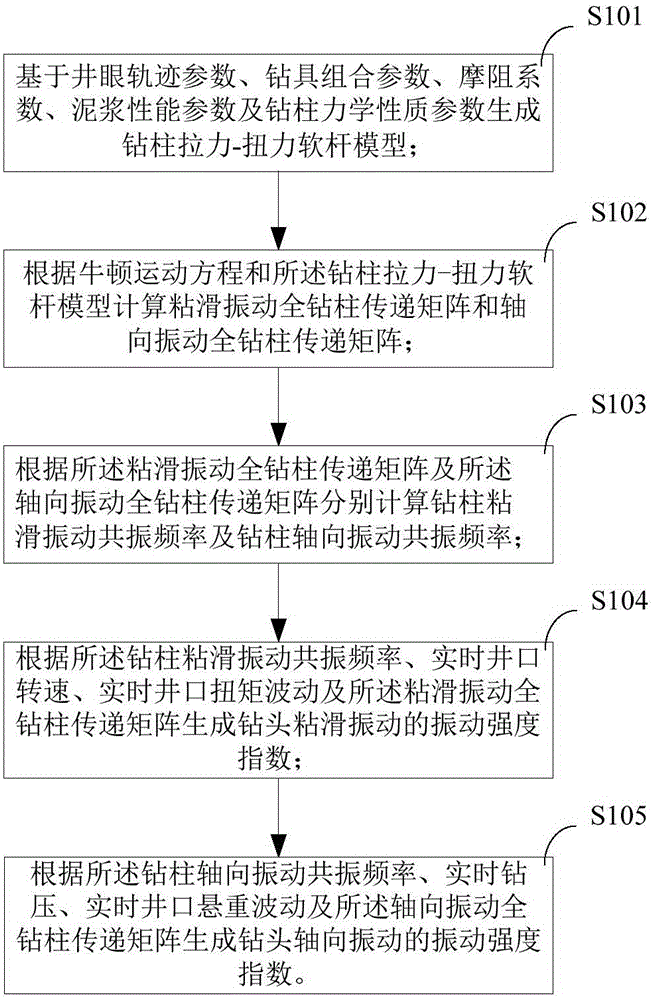
[0112] figure 1 is a schematic flow chart of the vibration monitoring method of the embodiment of the present invention. like figure 1 As shown, the vibration monitoring method includes steps:

[0113] S101: Generate a drill string tension-torque soft rod model based on wellbore trajectory parameters, drilling tool assembly parameters, friction coefficient, mud performance parameters and drill string mechanical property parameters;

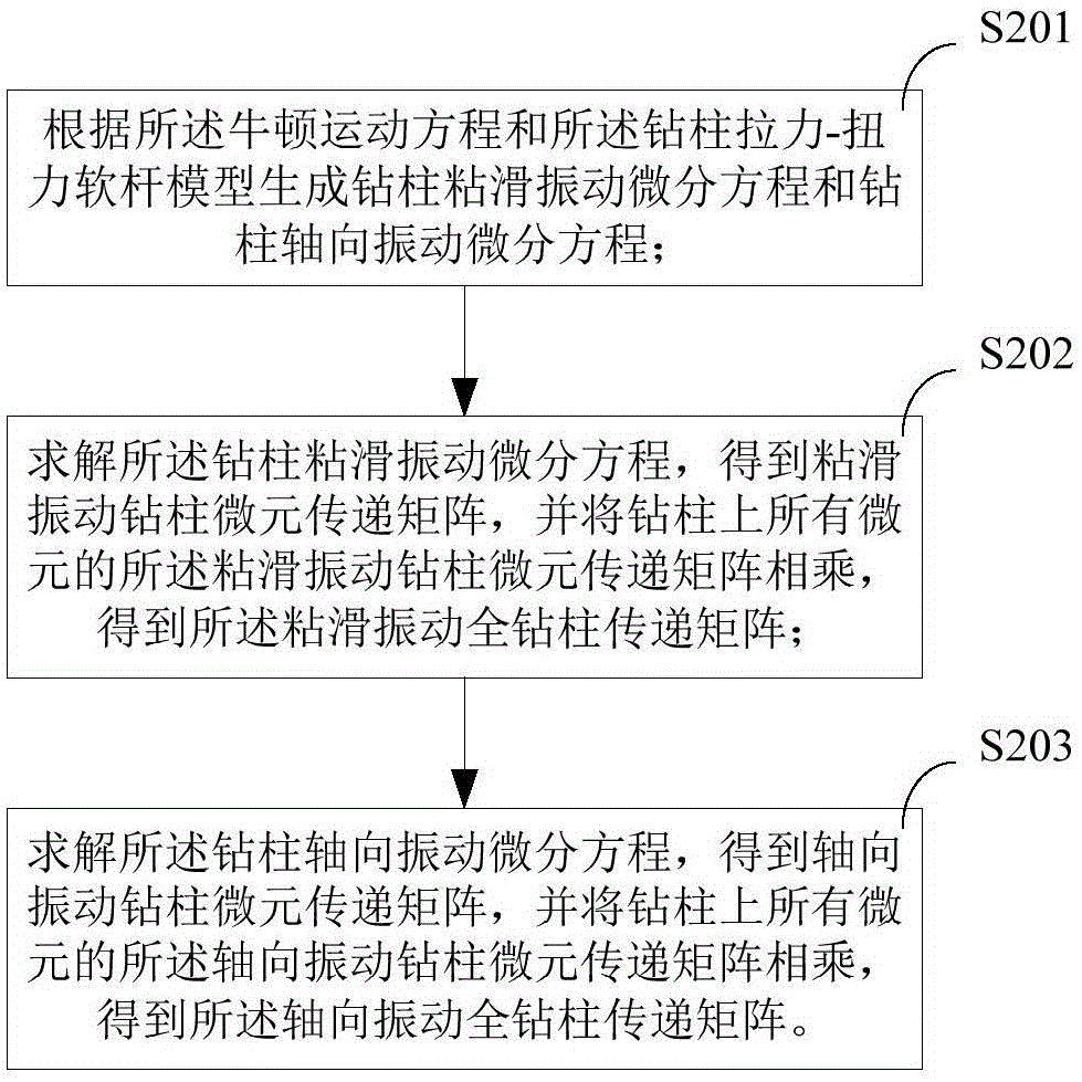
[0114] S102: Calculate the stick-slip vibration full drill string transfer matrix and the axial vibration full drill string transfer ...


PUM


Abstract

The invention provides a downhole vibration monitoring method. The method includes the steps that a drill stem tension-torsion soft-string model is generated on the basic of well track parameters, drilling assembly parameters, coefficients of friction resistance, mud performance parameters and drill stem mechanical property parameters; a stick-slip vibration drill stem transfer matrix and an axial vibration drill stem transfer matrix are calculated according to the Newton motion equation and the drill stem tension-torsion soft-string model; the stick-slip vibration resonant frequency of the drill stem and the axial vibration resonant frequency of the drill stem are calculated according to the stick-slip vibration drill stem transfer matrix and the axial vibration drill stem transfer matrix; the vibration strength index of stick-slip vibration of a drill bit is generated according to the stick-slip vibration resonant frequency of the drill stem, the real-time well mouth rotation speed, the well mouth torque fluctuation and the stick-slip vibration drill stem transfer matrix; and the vibration strength index of axial vibration of the drill bit is generated according to the axial vibration resonant frequency of the drill stem, the real-time drilling pressure, the well mouth hanging load fluctuation and the axial vibration drill stem transfer matrix. By means of the method, the downhole vibration amplitude can be judged visually and quantificationally.

Description

technical field [0001] The invention relates to the technical field of oil and gas exploration and development, in particular to a downhole vibration monitoring method. Background technique [0002] The drill string is an important tool in drilling construction, and it is the link between the ground drilling equipment and the bottom hole drill bit. The collision between the drill string and the well wall and the heterogeneity of the formation lead to the instability of the load on the drill bit, which makes the dynamic load transmitted to the drilling tool itself and the ground power system in the form of vibration, and finally causes the vibration of the entire drilling tool assembly, which leads to BHA (Bottom Hole Assembly) and instrument damage. [0003] Drill tool vibration is mainly divided into three types, axial vibration, lateral vibration and torsional vibration. Axial vibration is the phenomenon that the drill bit is out of contact with the formation instantaneo...

Claims


Application Information

Patent Timeline
Patent Type & Authority Applications(China)
IPC IPC(8): E21B44/00
Inventor 崔猛葛云华汪海阁陈志学王灵碧
Owner BC P INC CHINA NAT PETROLEUM CORP
Why Eureka
Try Eureka