
Exhaust gas sampling apparatus, exhaust gas analysis system and exhaust gas dilution method

A technology of sampling device and dilution flow, which is applied in the direction of sampling device, exhaust device, exhaust treatment device, etc., can solve the problems of large and complex system, and achieve the effect of simple structure

Inactive Publication Date: 2016-10-05
HORIBA LTD
View PDF5 Cites 0 Cited by
  • Summary
  • Abstract
  • Description
  • Claims
  • Application Information

AI Technical Summary

Problems solved by technology

Then, in order to be able to cope with various dilution rates, it is considered that the variable flow range of each flow controller has to be enlarged, which will lead to an increase in size and complexity of the system.

Method used


Image

  • Exhaust gas sampling apparatus, exhaust gas analysis system and exhaust gas dilution method
  • Exhaust gas sampling apparatus, exhaust gas analysis system and exhaust gas dilution method
  • Exhaust gas sampling apparatus, exhaust gas analysis system and exhaust gas dilution method

Examples


Embodiment Construction

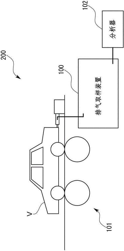
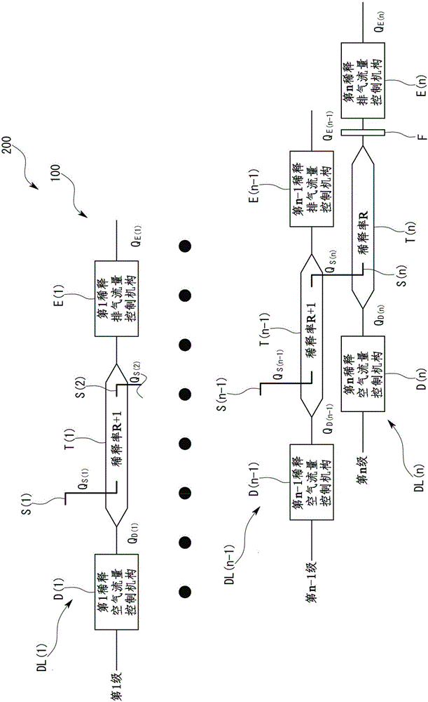
[0048] refer to figure 1 and figure 2 An exhaust gas analysis system 200 and an exhaust gas sampling device 100 according to one embodiment of the present invention will be described.

[0049] Such as figure 1 As shown, the exhaust gas sampling device 100 of this embodiment constitutes a part of an exhaust gas analysis system 200 for measuring the amount of particulate matter (hereinafter also referred to as PM) having a predetermined particle diameter contained in exhaust gas. More specifically, for example, for the installation pipe installed on the exhaust pipe of the vehicle V that is tested on the chassis dynamometer 101, the sampling pipe S of the exhaust gas sampling device 100 is inserted from the side of the installation pipe to the inside. . Then, a part of the original exhaust gas discharged from the vehicle V is sampled by the sampling pipe S, and diluted to a predetermined concentration by the exhaust gas sampling device 100 . The diluted exhaust gas diluted ...


PUM


Abstract

The present invention provides an exhaust gas sampling apparatus that makes it possible to simplify the entire system using a simple structure flow rate control mechanism having a small variable flow rate range as well as making the accuracy of an exhaust gas dilution ratio higher than before, the exhaust gas sampling apparatus is configured as an exhaust gas sampling apparatus that makes a multistage dilution. In addition, the exhaust gas sampling apparatus is configured to, given that a dilution ratio determined by an n-th diluter in a dilution flow path at an n-th stage as a final stage is R, make dilution ratios determined by diluters in dilution flow paths at the respective stages other than the n-th stage as the final stage substantially equal to (R+1).

Description

technical field [0001] The present invention relates to an exhaust gas sampling device for diluting exhaust gas through multi-stage dilution provided with a multi-stage dilution channel. Background technique [0002] For example, when measuring the amount of particulate matter (hereinafter also referred to as PM) with a predetermined particle diameter contained in exhaust gas, the exhaust gas is diluted at a large dilution rate, and the diluted exhaust gas passes through the filter at a predetermined flow rate. [0003] The greater the dilution rate, the more easily the influence of the flow rate error of the dilution air flowing into the diluter and the flow rate error of the exhaust gas obtained by the diluter appears in the accuracy of the dilution rate. Therefore, it is difficult to dilute the exhaust gas with the desired precision when the dilution rate becomes large in an exhaust gas sampling device provided with only one dilution channel. [0004] In order to solve s...

Claims


Application Information

Patent Timeline
Patent Type & Authority Applications(China)
IPC IPC(8): G01N1/22
CPCG01N1/2252G01N2001/2255G01N1/2205G01N2001/2264F01N11/007F01N9/00F01N3/05F01N3/021G01M15/102G01N15/06F01N2550/14G01N2015/0046
Inventor 大槻喜则
Owner HORIBA LTD
Learn More