Steel plate edge scanning and cutting control system based on laser distance measuring sensors

A laser ranging and edge scanning technology, used in welding/welding/cutting items, manufacturing tools, gas flame welding equipment, etc., can solve the problems of large steel plate size, time-consuming and laborious cutting accuracy, etc. High quality and manpower saving effect

Active Publication Date: 2016-10-12
佛山市中菱智控科技有限公司
View PDF6 Cites 5 Cited by
  • Summary
  • Abstract
  • Description
  • Claims
  • Application Information

AI Technical Summary

Problems solved by technology

Due to the large size of the steel plate produced by the rolling mill, at present, there is no suitable automatic detection system to identify its outline. The conventional two-dimensional outline recognition scheme can identify the outline of the steel plate. The structure of the two-dimensional outline recognition scheme includes wired laser, two-dimensional dimensional camera to take pictures, etc., but they can only recognize the outline of small-sized objects. Therefore, before the gantry flame plasma cutting machine cuts the steel plate, the edge of the steel plate can only be positioned manually by using measuring tools or by visual inspection. Cutting is time-consuming and labor-intensive and the cutting accuracy is low

Method used


Image

  • Steel plate edge scanning and cutting control system based on laser distance measuring sensors
  • Steel plate edge scanning and cutting control system based on laser distance measuring sensors
  • Steel plate edge scanning and cutting control system based on laser distance measuring sensors

Examples


Embodiment Construction

[0025] The following will clearly and completely describe the technical solutions in the embodiments of the present invention in conjunction with the accompanying drawings of the present invention. Obviously, the described embodiments are only some, not all, embodiments of the present invention. Based on the embodiments of the present invention, all other embodiments obtained by persons of ordinary skill in the art without creative efforts fall within the protection scope of the present invention.

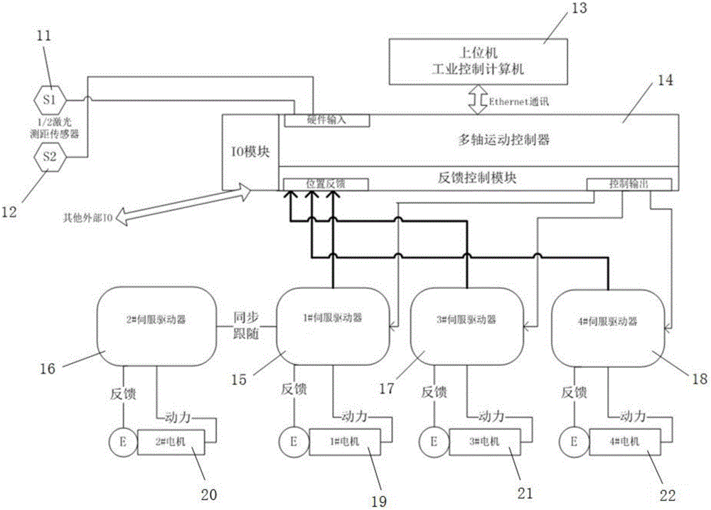
[0026] Such as figure 1 As shown, the steel plate edge scanning and cutting control system based on the laser ranging sensor in this embodiment. The steel plate edge scanning and cutting control system includes a first laser ranging sensor 11, a second laser ranging sensor 12, an upper computer industrial control computer 13, a multi-axis motion controller 14, 1# servo driver 15, 1# motor 19, 2# servo driver 16, 2# motor 20, 3# servo driver 17, 3# motor 21, 4# servo driver 18 and ...


PUM


Abstract

The invention discloses a steel plate edge scanning and cutting control system based on laser distance measuring sensors. The steel plate edge scanning and cutting control system based on the laser distance measuring sensors comprises the first laser distance measuring sensor, the second laser distance measuring sensor, an upper computer industrial control computer, a multi-axis movement controller, a 1# servo driver, a 1# motor, a 3# servo driver, a 3# motor, a 4# servo driver and a 4# motor, wherein the first laser distance measuring sensor and the second laser distance measuring sensor are connected with the multi-axis movement controller; the upper computer industrial control computer is in communication connection with the multi-axis movement controller; the 1# motor is connected with the 1# servo driver; the 3# motor is connected with the 3# servo driver; the 4# motor is connected with the 4# servo driver; and the multi-axis movement controller is provided with a feedback control module, and the 1# servo driver, the 3# servo driver and the 4# servo driver are all connected with the feedback control module. The steel plate edge scanning and cutting control system based on the laser distance measuring sensors can carry out automatic scanning and cutting on steel plates, manpower is saved, and the precision and quality of the cut steel plates are high.

Description

technical field [0001] The invention belongs to the technical field of scanning and cutting control systems in the steel material processing industry, and relates to a steel plate edge scanning and cutting control system based on a laser ranging sensor. Background technique [0002] The large-size (such as length, width and thickness: 33m*2m*15mm) steel plates produced by the rolling mill of the steelmaking plant are usually not regular rectangles, and their front, rear, left, and right edges have a certain degree of curvature, which needs to be cut off by a gantry flame plasma cutting machine The irregular part of the edge of the steel plate is cut into several small steel plates in the shape of "tofu block", which are used by downstream industries. Due to the large size of the steel plate produced by the rolling mill, at present, there is no suitable automatic detection system to identify its outline. The conventional two-dimensional outline recognition scheme can identify...

Claims


Application Information

Patent Timeline
Patent Type & Authority Applications(China)
IPC IPC(8): B23K7/10B23K101/18
CPCB23K7/102B23K2101/18
Inventor 曾超陶颖郁苗成
Owner 佛山市中菱智控科技有限公司
Why Eureka
Try Eureka