Control method for hydraulic lifting equipment

A technology of hydraulic lifting and control methods, applied in the direction of load hanging components, transportation and packaging, etc., can solve the problems of insufficient lifting capacity, limited lifting height and space, poor lifting synchronization, etc., to achieve convenient maintenance and balanced load distribution High performance and high synchronization

Active Publication Date: 2016-10-12
ZHEJIANG JINGGONG STEEL BUILDING GRP
View PDF3 Cites 6 Cited by
  • Summary
  • Abstract
  • Description
  • Claims
  • Application Information

AI Technical Summary

Problems solved by technology

[0004] The purpose of the present invention is to provide a control method for hydraulic lifting equipment, which can effectively overcome the shortcomings of existing steel structure construction lifting equipment, such as ...

Method used


Image

  • Control method for hydraulic lifting equipment
  • Control method for hydraulic lifting equipment
  • Control method for hydraulic lifting equipment

Examples


Embodiment Construction

[0013] Next, the preferred embodiments of the present invention will be described in further detail with reference to the accompanying drawings.

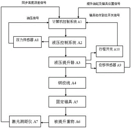
[0014] Such as figure 1 Shown is a schematic diagram of the composition and control relationship of the embodiments of the present invention. The control system includes a computer control system A1, a hydraulic control system A2, and a detection and monitoring system. The detection and monitoring system includes a laser rangefinder A7, a pressure sensor A8, and a displacement sensor. A9, and travel switch A10. The actuator mainly includes hydraulic lifter A3, steel strand A4, and fixed anchor A5. During the lifting construction, the hydraulic lifter A3 is installed on the lifting platform, and the lifting weight A6 is fixed to the steel strand A4 through the fixed anchor A5. When lifting, parameters such as the height of the lifting weight 6, the position signal of the lifting cylinder and the anchor, the pressure of the oil pressure...


PUM


Abstract

The invention belongs to the field of mechanical equipment and particularly relates to a control method for hydraulic lifting equipment. The control method specifically comprises the steps that a lifting instruction is sent out by a computer control system and transmitted to all hydraulic control systems through a communication protocol; and after the hydraulic control systems receive the instruction, a master-slave closed-loop synchronous control mode is adopted to enable all hydraulic lifters to synchronously lift and achieve the following steps that 1, lower anchorage devices are loosened in place in the initial position; 2, the movable parts of lifting oil cylinders go up in place; 3, the lower anchorage devices are clamped in place; 4, the movable parts of the lifting oil cylinders are slightly shrunk in place; 5, upper anchorage devices are loosened in place; 6, the lifting oil cylinders are shrunk in place; and 7, the upper anchorage devices are clamped in place, and operation returns to the step 1. The control method for the hydraulic lifting equipment has the advantages of being higher in structure adaptability, more reliable in operation, simple in mechanical structure, convenient to maintain and the like.

Description

Technical field [0001] The invention belongs to the field of mechanical equipment, and specifically relates to a control method of hydraulic lifting equipment. Background technique [0002] With the rapid development of the steel structure construction industry, the integrated design, manufacturing, and construction of high-rise and super high-rise buildings, large-scale exhibition halls, etc. have become the trend of the times. However, facing the large-scale and ultra-high-rise steel structure buildings, the existing steel Structural upgrading construction equipment will face greater challenges. First: The current lifting construction equipment is mainly cranes. When the lifting capacity of a single crane is insufficient or the stability of single-point lifting is poor, multiple cranes will be used for coordinated lifting. At this time, the synchronization control of the cranes is controlled by the operator. Poor performance, resulting in poor load distribution balance; Second...

Claims


Application Information

Patent Timeline
IPC IPC(8): B66C13/20B66C13/48
CPCB66C13/20B66C13/48
Inventor 邓伟平俞荣华郑光明张小英俞锡齐陈雄俞福利李翔
Owner ZHEJIANG JINGGONG STEEL BUILDING GRP
Why Eureka
Try Eureka