Assembly type concrete column partially and externally wrapped by H-shaped steel and energy dissipation steel plate shear wall structure

A technology of outsourcing concrete and steel plate shear walls, applied in the direction of walls, building components, building types, etc., can solve the problems of insufficient ductility and energy dissipation capacity, decreased bearing capacity, buckling instability of steel plates, etc., to improve the seismic performance and deformation. capacity, compressing the base cost, and reducing the effect of the structure's own weight

Inactive Publication Date: 2016-10-12
HOHAI UNIV
View PDF5 Cites 10 Cited by
  • Summary
  • Abstract
  • Description
  • Claims
  • Application Information

AI Technical Summary

Problems solved by technology

[0003] Aiming at the shortcomings of concrete shear wall ductility and insufficient energy consumption, a new type of lateral force resistance system—steel plate shear wall was developed in the 1970s. The traditional embedded steel plate shear wall or single-sided steel plate shear wall, due to The concrete steel plate shear wall has high rigidity, and when the lateral movement of the earthquake is small, the corners and the frame are squeezed together, and the concrete is easy to crack and peel off, so that the restraint on the steel plate is reduced, and the steel plate is prone to local buckling and instability, resulting in a large bearing capacity. Decrease in magnitude, insufficient ductility and energy dissipation capacity

Method used


Image

  • Assembly type concrete column partially and externally wrapped by H-shaped steel and energy dissipation steel plate shear wall structure
  • Assembly type concrete column partially and externally wrapped by H-shaped steel and energy dissipation steel plate shear wall structure
  • Assembly type concrete column partially and externally wrapped by H-shaped steel and energy dissipation steel plate shear wall structure

Examples


Embodiment Construction

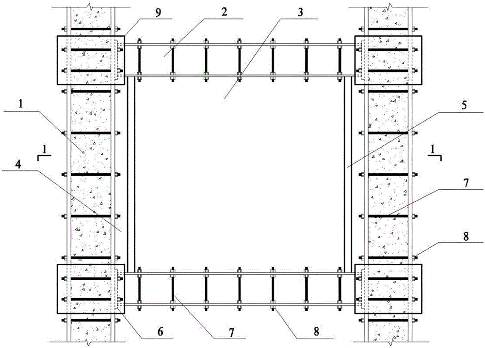
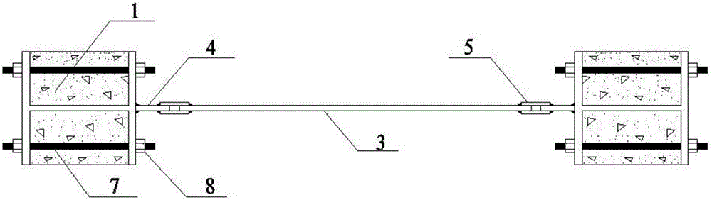
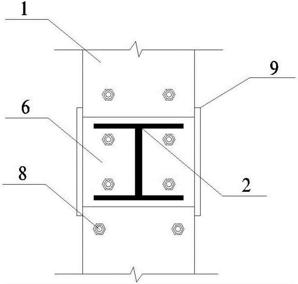
[0017] Such as figure 1 , figure 2 with image 3 As shown, the present invention provides a kind of fabricated H-shaped steel partially outsourcing concrete column-energy-dissipating steel plate shear wall structure including vertical frame column 1, horizontal frame beam (transverse beam) 2 and the frame beam and frame column Steel plate shear walls between 3.

[0018] Among them, the steel plate shear wall adopts steel with low yield strength and high ductility, and the frame column adopts H-shaped steel concrete column with double-sided flange and tie rod 7. The horizontal beam adopts H-shaped steel beams with upper and lower flange plates and restraint rods. The restraint rods on the H-shaped steel flange plates of the beams and columns are drilled on the flange plates and penetrated by full-thread screws and connected with high-strength friction bolts 8 . The end of the H-shaped steel beam is provided with an end plate 6, and the end plate is welded to the H-shaped st...


PUM

PropertyMeasurementUnit
diameteraaaaaaaaaa
strengthaaaaaaaaaa
strengthaaaaaaaaaa

Abstract

The invention discloses an assembly type concrete column partially and externally wrapped by H-shaped steel and energy dissipation steel plate shear wall structure. The shear wall structure comprises frame columns, transverse beams and a shear wall. Each frame column comprises H-shaped steel, a plurality of transverse pull bars fixed to flange plates on the two sides of the H-shaped steel in the length direction of the H-shaped steel, concrete filled up into an accommodating cavity formed by webs of the H-shaped steel and the flange plates, side plates welded to the beam-column joints and attachment plates welded to the flange plates of the H-shaped steel. Each transverse beam comprises an H-shaped steel plate, restraint pull bars fixed to flange plates on the two sides of the H-shaped steel plate in the length direction of the H-shaped steel plate and end plates fixed to the tail ends of the H-shaped steel plate. A steel plate is adopted as the shear wall. The two ends of the shear wall are fixedly connected with the attachment plates through clamping plates. The seismic performance and deformability of the frame shear wall can be effectively improved, the self-weight of the structure can be effectively lowered, seismic response can be reduced, the foundation cost is cut, and the shear wall structure is particularly suitable for reinforcement and reconstruction of existing buildings.

Description

technical field [0001] The invention belongs to the field of construction, in particular to an assembled H-shaped steel part-wrapped concrete column-energy-dissipating steel plate shear wall structure. Background technique [0002] The shear wall mainly bears the horizontal load caused by wind load or earthquake, and is a kind of horizontal lateral force-resisting member commonly used in high-rise building structures. The current frame-shear and tube-in-tube systems that are popular in the design of super high-rise structures have their own defects. The ductility and stiffness of reinforced concrete shear walls or core tubes and steel frames are seriously mismatched. Under the action of strong earthquakes, since the reinforced concrete shear wall or core tube as the first anti-seismic defense line bears 85% of the horizontal seismic force, it will soon be cracked and crushed, resulting in a sharp degradation of stiffness and ductility, which is not conducive to the subsequen...

Claims


Application Information

Patent Timeline
Patent Type & Authority Applications(China)
IPC IPC(8): E04B2/60E04H9/02E04B1/98C04B28/00C04B14/02C04B14/06C04B14/42C04B18/08C04B24/42
CPCC04B28/00E04B2/60E04H9/024C04B14/06C04B14/42C04B18/08C04B14/02C04B24/42Y02W30/91
Inventor 伍凯桑胜涛陈峰南洋张贺
Owner HOHAI UNIV
Why Eureka
Try Eureka