Bottom hole pressure real-time prediction and control method

A bottomhole pressure and real-time prediction technology, which is applied in the wellbore pressure control of mud underbalanced/managed pressure drilling and conventional drilling, can solve the problems of difficult well control risk control, bottomhole pressure prediction, and key coefficient determination. , to avoid complex multiphase flow models, reduce drilling costs, and simplify the model

Inactive Publication Date: 2016-10-12
CHINA NAT PETROLEUM CORP CHUANQING DRILLING ENG CO LTD
View PDF10 Cites 26 Cited by
  • Summary
  • Abstract
  • Description
  • Claims
  • Application Information

AI Technical Summary

Problems solved by technology

[0006] The purpose of the present invention is to provide a method for real-time prediction and control of bottomhole pressure aiming at the defects and deficiencies of the above-mentioned prior art. By adopting this method, it is possible to avoid the multiphase pressure loss caused by the traditional pressure loss calculation using annular space multiphase flow. Problems such as complex flow mod

Method used


Image

  • Bottom hole pressure real-time prediction and control method
  • Bottom hole pressure real-time prediction and control method
  • Bottom hole pressure real-time prediction and control method

Examples


Embodiment 1

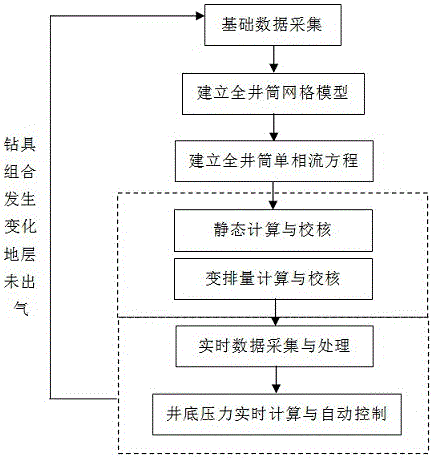
[0043] As the best implementation mode of the present invention, its steps include:

[0044] a. Basic data collection

[0045] Before drilling, if the formation does not produce gas, run downhole pressure gauges for test drilling, and carry out variable displacement tests. The displacement will be reduced by 2-5L / s each time, and the time interval between each time should not be less than 2min. Pressure gauge data, and one-to-one correspondence with standing pressure and displacement data, record and store in the database.

[0046] Obtain basic parameters, including: wellbore structure, wellbore trajectory, drilling tool assembly, drill bit size and number of nozzles, rheological parameters of drilling fluid, designed safe density window, and formation temperature.

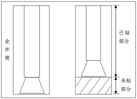
[0047] Wellbore trajectory includes two parts of data. One part is the actual wellbore trajectory of the previous drilling trip, and the other part comes from the drilling design, which is the undrilled design t...

Embodiment 2

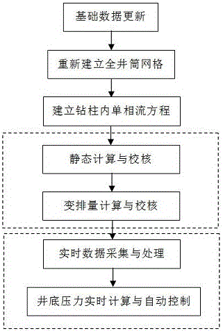
[0098] On the basis of Embodiment 1, the present invention further includes step h, real-time calculation and automatic control of the bottom hole pressure after the drilling tool assembly changes:

[0099] In the next drilling trip, the drilling tool assembly may change, and the bottom hole pressure may also change, and the real-time calculation of the bottom hole pressure is terminated.

[0100] If the formation is not out of gas, steps a-g will be repeated.

[0101] Gas is produced in the formation, and the annulus is already a multiphase flow. The relationship between well depth and pressure on the annulus section cannot be established by using the single-phase flow formula. Therefore, another set of procedures will be used.


PUM


Abstract

The invention discloses a bottom hole pressure real-time prediction and control method. The method includes the following steps that a, essential data are acquired, wherein bottom hole pressure meter data in the test drilling process are obtained, and the essential data of a well are obtained; b, a whole-shaft grid model is established; c, a whole-shaft single-phase flow equation is established; d, static computation and checking are conducted; e, variable displacement computation and checking are conducted; f, real-time data acquisition and processing are conducted; and g, bottom hole pressure real-time computation and automatic control are conducted, wherein the step g includes the content that all the data are called for conducting bottom hole pressure real-time computation and control. By the adoption of the method, the problems that a multi-phase flow model is complex, a flow pattern is difficult to distinguish, and key coefficients are difficult to determine due to the utilization of annulus multi-phase flow pressure loss computation traditionally can be solved, and the computation accuracy of the bottom hole pressure is improved.

Description

technical field [0001] The invention belongs to the technical field of exploration and development of oil and gas fields, and in particular relates to a wellbore pressure control method for conventional drilling and mud underbalanced / pressure-managed drilling. Background technique [0002] In the process of conventional drilling and mud underbalanced / managed pressure drilling, there is always a well control risk after formation gas is released, and real-time, fast and accurate prediction of bottom hole pressure is very critical for well control. Moreover, the real-time prediction and control of bottomhole pressure is also the key core technology of well control automation in future automated drilling. [0003] In conventional drilling, mud underbalanced / managed pressure drilling, the bottom hole pressure data is usually measured by the APWD (Annular Pressure While Drilling) or the PWD (Pressure While Drilling). However, in some high-temperature and high-pressure wells, the ...

Claims


Application Information

Patent Timeline
IPC IPC(8): E21B47/06E21B21/08
CPCE21B47/06E21B21/08
Inventor 魏强肖润德薛秋来董斌杨玻李枝林陶序莹
Owner CHINA NAT PETROLEUM CORP CHUANQING DRILLING ENG CO LTD
Why Eureka
Try Eureka