
Dynamic sealing and pressure compensation structure for shear valve slurry pulser

A technology of pressure compensation and mud pulse, which is applied in the direction of engine sealing, engine components, mechanical equipment, etc., can solve the problems of short working time of pressure compensation mechanism, complicated pressure compensation structure, inconvenient maintenance, etc., and achieve simple operation and maintenance , Reliable mechanical connection and effective sealing effect

Active Publication Date: 2016-10-12
CHINA NAT OFFSHORE OIL CORP +1
View PDF6 Cites 10 Cited by
  • Summary
  • Abstract
  • Description
  • Claims
  • Application Information

AI Technical Summary

Problems solved by technology

The movement of the piston balances the external pressure; it has the disadvantages of complex pressure compensation structure, many instrument parts, and inconvenient maintenance; at the same time, the oil inside the oil chamber leaks outward, and the working time of such a pressure compensation mechanism is short

Method used


Image

  • Dynamic sealing and pressure compensation structure for shear valve slurry pulser
  • Dynamic sealing and pressure compensation structure for shear valve slurry pulser
  • Dynamic sealing and pressure compensation structure for shear valve slurry pulser

Examples


Embodiment Construction

[0042] Embodiments of the present application will be described in detail below with reference to the accompanying drawings. It should be noted that, in the case of no conflict, the embodiments in the present application and the features in the embodiments can be combined arbitrarily with each other.

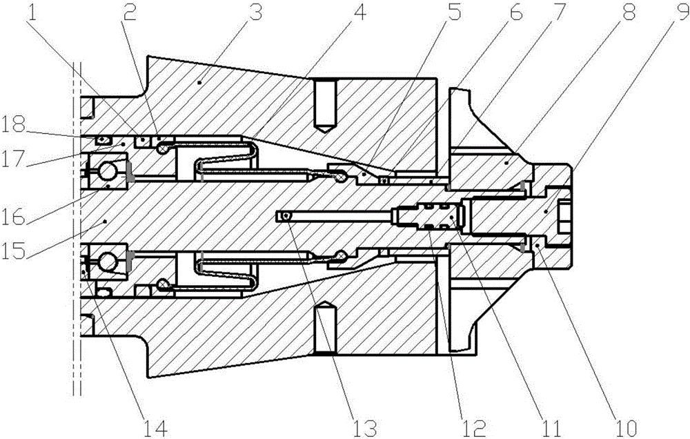
[0043] The present invention proposes the technical scheme by comprehensively considering dynamic sealing, pressure compensation, motor oil immersion, motor internal flow channel, rubber cartridge structure protection, etc.; among them, dynamic sealing, the rotor (valve plate) of the shear valve pulser When working, it swings back and forth. In the transmission system from the output shaft of the power end to the rotor, the rotor directly contacts the mud, and the output shaft of the motor must have a reliable seal. Structurally, a dynamic seal should be used. Pressure compensation, the shear valve pulser needs to bear the influence of the static pressure of the mud column, the...


PUM


Abstract

The invention discloses a dynamic sealing and pressure compensation structure for a shear valve slurry pulser. The dynamic sealing and pressure compensation structure comprises a rubber cylinder structure, wherein the rubber cylinder structure is arranged in an annular cavity formed by a cavity structure of a stator and an output shaft, one end of the rubber cylinder sleeves on the outer side of the output shaft, and the other end of the rubber cylinder structure sleeves on the outer side of a pulser shell; the stator sleeves on the outer side of the output shaft of a motor, and a rotor is connected to the tail end of the output shaft of the motor; and a cavity structure is arranged in the stator, the rubber cylinder structure is arranged in the annular cavity formed between the cavity part, close to the rotor, of the cavity structure and the output shaft, and the pulser shell is mounted in the annular cavity between the cavity part, far from the rotor, of the cavity structure and the output shaft. The invention relates to but is not limited to oil exploration equipment. By virtue of the dynamic sealing and pressure compensation structure, the configuration of the optimal dynamic sealing mechanism can be realized, and the service life of a dynamic sealing part can be effectively prolonged; and meanwhile, the configuration of an optimal pressure compensation mechanism can be realized, and the routing process of short sections in an instrument can be effectively optimized.

Description

technical field [0001] This application relates to but not limited to oil exploration equipment, especially a dynamic seal and pressure compensation structure of a shear valve mud pulser. Background technique [0002] The Measurement While Drilling (MWD) system can measure parameters such as well deviation, well deviation azimuth, downhole torque, drill bit load-bearing, natural gamma ray, and resistivity. With the development of petroleum engineering, in the 1980s, on the basis of the original measurement-while-drilling system MWD, a number of parameter sensors for formation evaluation were added, such as compensated dual lateral resistivity, natural gamma ray, azimuth neutron density, Acoustic waves, compensated neutron density, etc.; a system composed of these instruments is often called a logging while drilling system (Logging While Drilling: LWD). MWD and LWD are the key technologies to complete large-angle and horizontal well drilling, real-time well site data acquisi...

Claims


Application Information

Patent Timeline
Patent Type & Authority Applications(China)
IPC IPC(8): E21B47/20F16J15/16
CPCE21B47/20F16J15/16
Inventor 王智明陆庆超张峥张爽姜天杰
Owner CHINA NAT OFFSHORE OIL CORP
Learn More