
Waste gas afterheat recovery heat exchanger

A waste heat recovery and heat exchanger technology, which is applied in the field of heat recovery devices and exhaust gas waste heat recovery heat exchangers, can solve problems such as clogging and difficult cleaning, and achieve the effect of reducing cycle working pressure, reducing manufacturing requirements, and fully exchanging heat

Active Publication Date: 2016-10-12
XI AN JIAOTONG UNIV
View PDF4 Cites 6 Cited by
  • Summary
  • Abstract
  • Description
  • Claims
  • Application Information

AI Technical Summary

Problems solved by technology

[0005] The purpose of the present invention is to provide an exhaust gas waste heat recovery heat exchanger that effectively solves the problem that the heat exchanger is blocked and difficult to clean during the waste gas waste heat recovery process

Method used


Image

  • Waste gas afterheat recovery heat exchanger
  • Waste gas afterheat recovery heat exchanger
  • Waste gas afterheat recovery heat exchanger

Examples


Embodiment Construction

[0036] The specific embodiments of the present invention will be described in detail below in conjunction with the accompanying drawings.

[0037] In this article, if there is no special explanation, when it comes to formulas, " / " means division, and "×" and "*" mean multiplication.

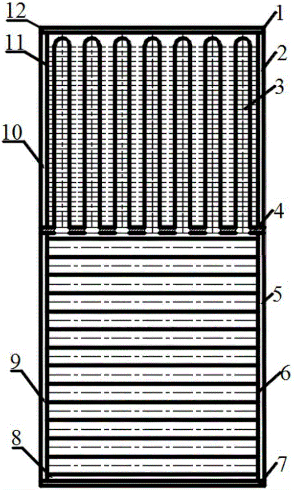
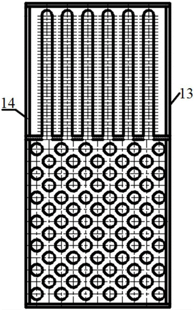
[0038] see figure 1 , 2. The present invention includes a heat exchange housing 1 and a thermal insulation sealing plate 14 installed on the front end surface of the heat exchange housing 1 and a thermal insulation sealing plate 13 on the rear end surface. Parallel sealing partitions 4, the sealing partitions 4 divide the heat exchanger into a hot end cavity and a cold end cavity;

[0039] The main part of the hot end cavity is the heat pipe evaporation chamber 8, and there are multiple rows of light pipes 6 arranged in the heat pipe evaporation chamber 8, the light pipes 6 are parallel to the bottom surface of the heat exchange shell 1, and the two ends of the light pipes 6 are respectively arr...


PUM


Abstract

The invention discloses a waste gas afterheat recovery heat exchanger. The waste gas afterheat recovery heat exchanger mainly consists of a heat end cavity, a cold end cavity, a sealing separation plate, an intensified heat exchange condensation pipe bundle and an evaporation light pipe bundle; an inner cavity of a cold end fin pipe is communicated with the upper wall of a heat evaporation cavity through welding; during working, smoke containing afterheat passes through the internal of a pipe at a hot end to heat liquid in the heat end cavity for gasification; steam enters from a small hole, communicated with the internal of an intensified heat exchange pipe, on the sealing separation plate; heated gas flows out of an intensified heat exchange pipe bundle, so that the steam in the pipe is condensed; the heat is transferred to the heated gas; and the condensed liquid flows back into the heat end cavity under the effect of gravity for recycling. Compared with the prior art, the waste gas afterheat recovery heat exchanger effectively solves the problems of blockage and difficult cleaning in the waste gas afterheat recovery process.

Description

technical field [0001] The invention belongs to the field of energy saving and emission reduction, and relates to a heat recovery device, in particular to a waste gas waste heat recovery heat exchanger. Background technique [0002] According to the survey, the total waste heat resources of various industries account for 17%-67% of their total fuel consumption, and the recyclable waste heat resources are about 60% of the total waste heat resources. At present, many mechanical equipment will produce a large amount of exhaust gas (smoke) during the working process. The current common practice is to directly discharge it into the atmosphere, which wastes a lot of heat energy and pollutes the environment. Due to the working environment, this part of the exhaust gas often contains impurities such as dust, fiber and oil. At present, the commonly used exhaust gas waste heat recovery devices include tube-and-tube type, rotary type, plate heat exchanger and heat pipe heat exchanger,...

Claims


Application Information

Patent Timeline
IPC IPC(8): F28D15/02F28F1/42F28F19/00
CPCF28D15/02F28F1/42F28F19/00
Inventor 陶文铨田恩金宇冀文涛何雅玲
Owner XI AN JIAOTONG UNIV
Learn More