Laser ranging device and laser ranging method thereof

A technology of laser distance measurement and laser signal, which is applied in the direction of measuring device, radio wave measurement system, electromagnetic wave re-radiation, etc. It can solve the problems of echo pulse broadening, output time difference, and affecting the measurement accuracy of laser range finder. Achieve the effect of simple circuit structure and strong adaptability

Inactive Publication Date: 2016-10-12
SHANGHAI SLAMTEC
View PDF2 Cites 28 Cited by
  • Summary
  • Abstract
  • Description
  • Claims
  • Application Information

AI Technical Summary

Problems solved by technology

Compared with the constant ratio timing method and the high-pass time method, the time identification circuit has a simple structure, low price, and strong anti-interference performance, but after the emitted laser pulse interacts with the target object, due to the difference in target surface characteristics (such as roughness, inclination etc.), which tend to cause broadening or deformation of the echo pulse
At the same time, the l

Method used


Image

  • Laser ranging device and laser ranging method thereof
  • Laser ranging device and laser ranging method thereof
  • Laser ranging device and laser ranging method thereof

Examples


Embodiment Construction

[0037] In order to make the technical content disclosed in this application more detailed and complete, reference may be made to the drawings and the following various specific embodiments of the present invention, and the same symbols in the drawings represent the same or similar components. However, those skilled in the art should understand that the examples provided below are not intended to limit the scope of the present invention. In addition, the drawings are only for schematic illustration and are not drawn according to their original scale.

[0038] The specific implementation manners of various aspects of the present invention will be further described in detail below with reference to the accompanying drawings.

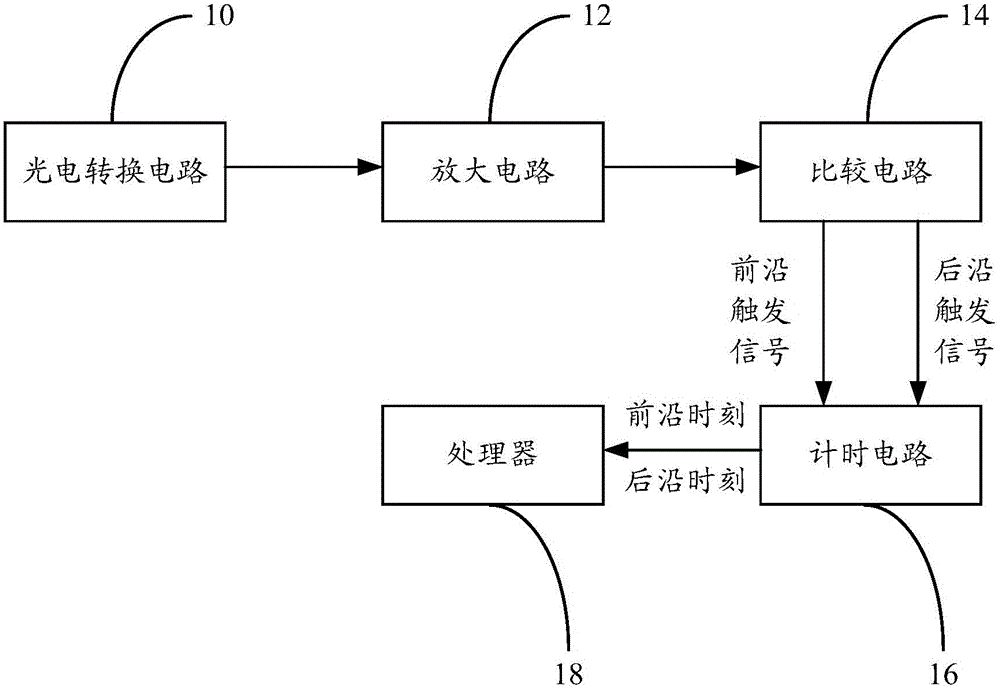
[0039] figure 1 According to an embodiment of the present invention, a structural block diagram of a laser distance measuring device based on leading time identification technology is shown.

[0040]As mentioned in the background art section, although the...


PUM


Abstract

The invention provides a laser ranging device and a laser ranging method thereof. The device includes: a photoelectric conversion circuit, used to convert the laser signal into a first electrical signal; an amplifying circuit, used to amplify the first electrical signal and output a second electrical signal; a comparison circuit, used to convert the second electrical signal The voltage value during the leading edge period and the voltage value during the trailing edge period are respectively compared with a preset threshold voltage in real time to obtain a leading edge trigger signal and a trailing edge trigger signal; the timing circuit is used to obtain the corresponding first moment and the second Two moments; and a processor with a built-in algorithm, used to obtain the pulse width value of the second electrical signal according to the time difference between the two moments. The present invention obtains the rough value of the measured distance through the frontier time identification technology, and at the same time obtains the pulse width of the echo signal, and the processor uses the relationship between the distance and the pulse width to call the algorithm to compensate, and obtain the high-precision distance measurement value at the same time The reflectivity of the target object is also obtained.

Description

technical field [0001] The invention relates to a laser ranging technology, in particular to a laser ranging method based on the frontier time identification technology. Background technique [0002] In the prior art, the laser range finder obtains distance information mainly by measuring the flight time of laser pulses. For example, a pulsed laser rangefinder uses a laser as a light source and a laser as a carrier. According to the principle of time-of-flight, the distance is measured by detecting the time difference between the laser emission pulse and the laser echo pulse. Specifically, the laser rangefinder includes a laser transmitter and a laser receiver. The laser transmitter emits a pulsed laser into the space. After the pulsed laser signal hits the surface of the target object, its echo signal is captured by the laser receiver. The distance between the target object and the laser rangefinder can be calculated by the time difference between the moment when the laser...

Claims


Application Information

Patent Timeline
IPC IPC(8): G01S17/08
CPCG01S17/08
Inventor 刘健徐磁张扬陈士凯李宇翔林凌刘义春黄珏珅
Owner SHANGHAI SLAMTEC
Why Eureka
Try Eureka