

Fuel cell with spatial structural MEA (membrane electrode assembly)
A space structure, fuel cell technology, applied in the direction of fuel cells, fuel cell components, solid electrolyte fuel cells, etc., can solve the problems affecting the direct transmission of gas, battery heating, occupation, etc., to increase the reactive area and reduce Fuel waste, enhanced gas transmission effect
- Summary
- Abstract
- Description
- Claims
- Application Information
AI Technical Summary
Problems solved by technology
Method used
Image

Examples
Embodiment Construction
[0037] The following examples further illustrate the technical solutions of the present invention, but are not intended to limit the protection scope of the present invention.
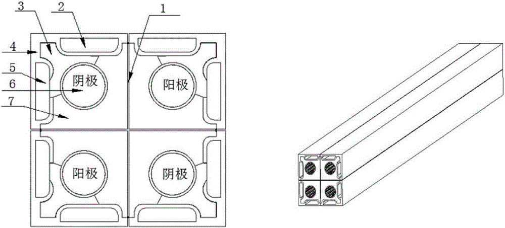
[0038] Cross type MEA fuel cell of the present invention, as attached figure 1 As shown, it includes space structure MEA1, diffusion layer (GDL) (3 and 7), reaction gas channel 6, pole plate 4, water channel (2 and 5);
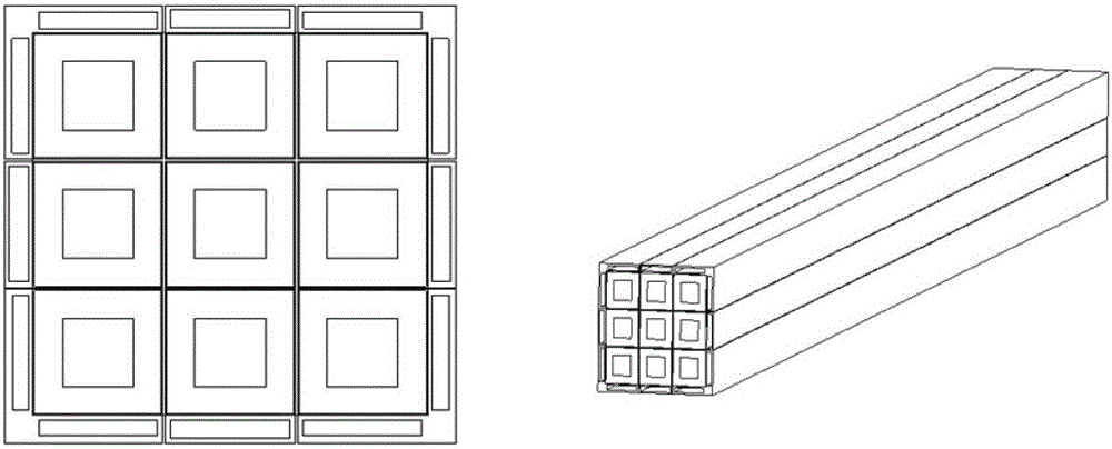
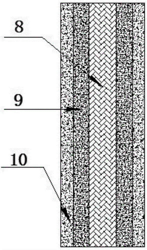
[0039] The spatial structure MEA can be a well-shaped, cross-shaped or honeycomb-shaped network structure, refer to the attached Figure 4 As shown; the MEA is arranged sequentially from the center to both sides in the manner of the proton exchange membrane 8, the catalytic layer 9, and the microporous layer 10, referring to the attached image 3 shown. When the spatial structure MEA is a well-shaped or honeycomb structure, the reactant gas channel not only transports gas but also acts as a plate to conduct current.
[0040] The diffusion layer presents a tubular structure with a s...
PUM
| Property | Measurement | Unit |
|---|---|---|
| Film thickness | aaaaa | aaaaa |
| Thickness | aaaaa | aaaaa |
Abstract
Description
Claims
Application Information