
S-waveband light-controlled phased array unit antenna

A unit antenna, phased array technology

Inactive Publication Date: 2016-10-12
WUYI UNIV
View PDF3 Cites 12 Cited by
  • Summary
  • Abstract
  • Description
  • Claims
  • Application Information

AI Technical Summary

Problems solved by technology

[0006] The purpose of the present invention is to overcome the shortcoming of prior art, propose a kind of S-band optically controlled phased array unit antenna, this antenna solves the problem that the gain of traditional quasi-Yagi antenna and relative bandwidth need to be enhanced

Method used


Image

  • S-waveband light-controlled phased array unit antenna
  • S-waveband light-controlled phased array unit antenna
  • S-waveband light-controlled phased array unit antenna

Examples


Embodiment Construction

[0020] The content of the present invention will be further described below in conjunction with the accompanying drawings.

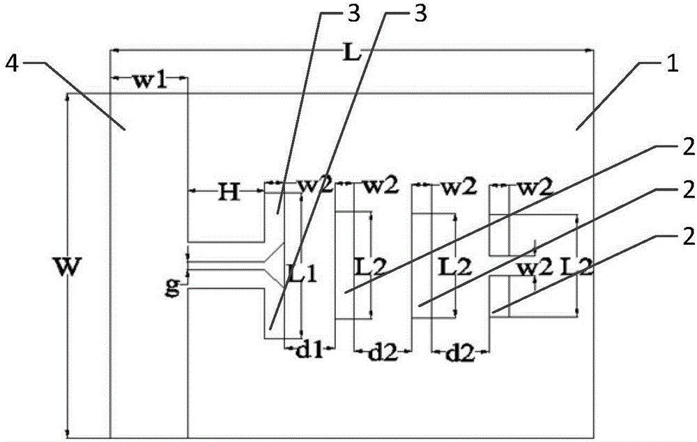
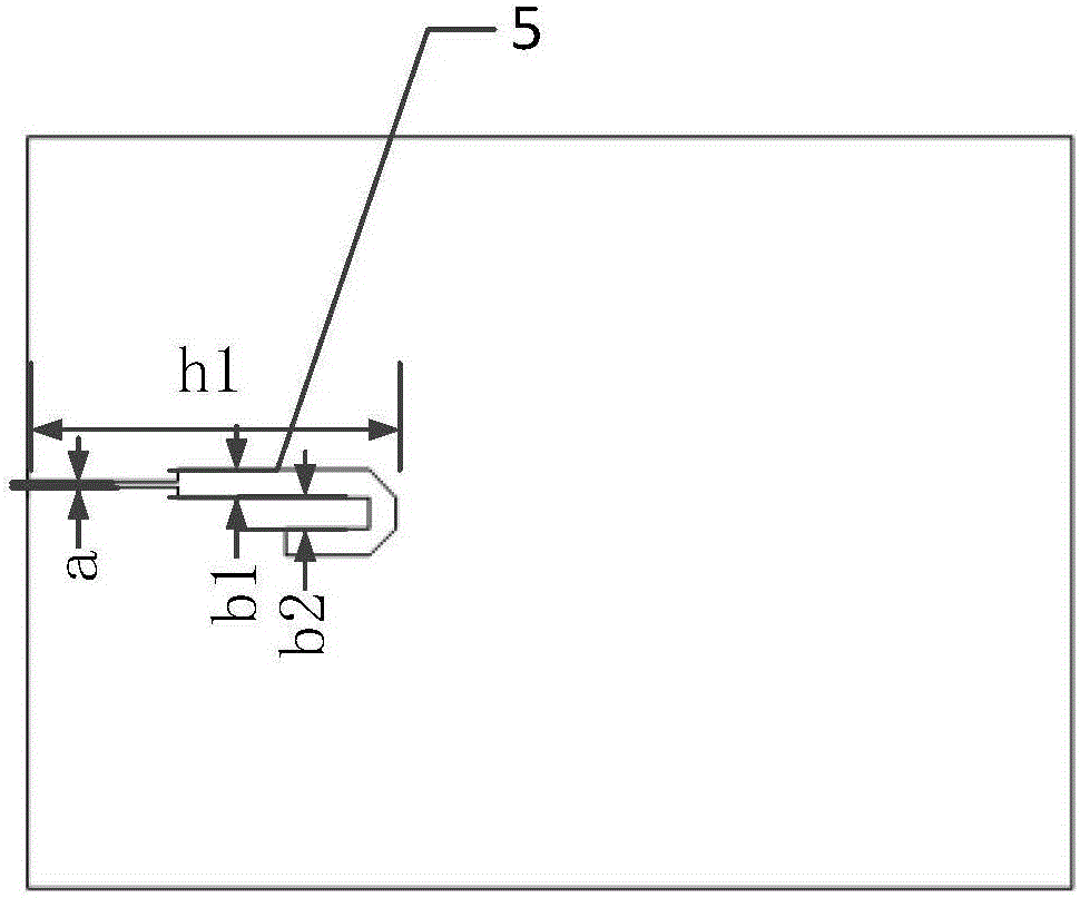
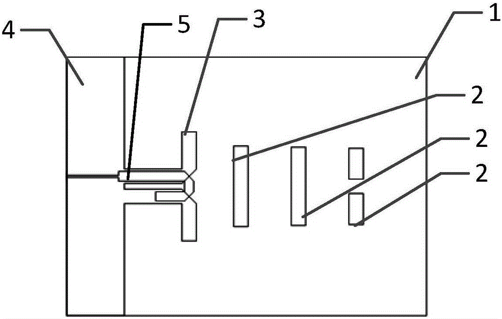
[0021] Examples such as figure 1 , 2 As shown in and 3, an S-band optically controlled phased array unit antenna includes: a dielectric substrate 1, three directors 2, a pair of excitation oscillators 3, a reflection oscillator 4, and a microstrip feeder 5; the dielectric substrate 1 FR4 material is used, its relative permittivity is 4.4, loss tangent is 0.025, and thickness is 1.6mm; on the front of the dielectric substrate 1, there are copper-clad directors 2, exciting vibrators 3 and reflective vibrators 4, three of which are guiding The device 2, the exciting vibrator 3 and the reflecting vibrator 4 are arranged on the dielectric substrate in sequence from top to bottom, the three directors 2 are located in the middle and upper part of the dielectric substrate 1, and the exciting vibrator 3 is connected to the reflecting vibrator 4 and located in th...


PUM


Abstract

The invention discloses an S-waveband light-controlled phased array unit antenna and relates to the technical field of wireless communication. The S-waveband light-controlled phased array unit antenna comprises a medium substrate, three directors, a pair of excitation oscillators, a reflection oscillator and a microstrip feed line, wherein the medium substrate comprises a front surface and a back surface, the directors, the excitation oscillators and the reflection oscillator are disposed at the front surface of the medium substrate, and the microstrip feed line is disposed at the back surface of the medium substrate; and the front surface of the medium substrate is provided with the copper-coated directors, the excitation oscillators and the reflection oscillator, and the three directors, the excitation oscillators and the reflection oscillator are successively arranged on the medium substrate from top to bottom. Compared to the prior art, the S-waveband light-controlled phased array unit antenna has the following advantages: simulation is carried out through Ansoft HFSS electromagnetic simulation software, a comparison is made with an actual test of an antenna, results show that the relative bandwidth of a standing-wave ratio (VSWR)2 reaches 40%, and the maximum gain at a center frequency point 2.4GHz is 6dB.

Description

technical field [0001] The invention relates to the technical field of wireless communication, in particular to an S-band optically controlled phased array unit antenna. Background technique [0002] In recent years, various requirements have led to the continuous development of phased array technology, and optically controlled phased array antennas have become the focus of scholars from all over the world. For example, in modern warfare, in order to improve the ability of phased array radar to distinguish and identify targets and solve the problem of radar imaging of targets, radars are required to have a large instantaneous signal bandwidth. At the same time, in order to reduce the probability of radar signals being intercepted and the threat of anti-radiation missiles, spread-spectrum signals with large instantaneous bandwidths are usually used. However, when the phased array radar antenna based on the phase shifter performs wide-angle scanning, the instantaneous bandwid...

Claims


Application Information

Patent Timeline
Patent Type & Authority Applications(China)
IPC IPC(8): H01Q1/38H01Q1/50H01Q1/48H01Q19/10
CPCH01Q1/38H01Q1/48H01Q1/50H01Q19/10
Inventor 张昕汤恒亮李继岚
Owner WUYI UNIV
Learn More