Conformal spherical antenna array

An antenna array and antenna technology, which is applied in the direction of separately energized antenna array, antenna support/installation device, radiation element structure, etc., can solve the difficulty of conformal array antenna pattern synthesis and the difficulty of conformal array antenna polarization control , Conformal antenna unit mutual coupling analysis difficulties and other problems, to achieve the effect of reducing material cost and weight, ensuring performance, and low production cost

Active Publication Date: 2016-10-12
成都泰格微电子研究所有限责任公司
View PDF5 Cites 13 Cited by
  • Summary
  • Abstract
  • Description
  • Claims
  • Application Information

AI Technical Summary

Problems solved by technology

At the same time, the radiation polarization of non-planar array elements is not uniform, so it may lead to high cross-polarization
[0005] The (ellipsoid) spherical structure is difficult to process and the cost is high. The design difficulties mainly include the following points: 1. It is difficult to analyze the characteristics of (ellipsoid) spherical conformal antenna elements and the mutual coupling between elements. 2. The conformal It is difficult to synthesize array antenna patterns, 3. Difficult to control the polarization of conformal array antennas, 4. Complex beamforming and control, 5. Difficult to test (calibrate)

Method used


Image

  • Conformal spherical antenna array
  • Conformal spherical antenna array
  • Conformal spherical antenna array

Examples


Embodiment 1

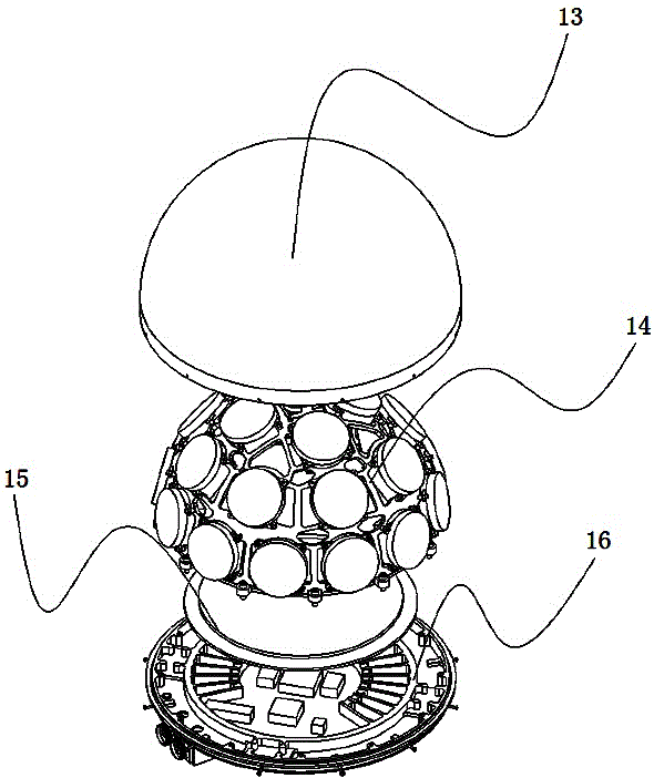
[0029] Such as figure 1 , Figure 3~Figure 7 As shown, a conformal spherical antenna array includes a radome 13, an antenna array 14, a shield 15, a base plate 16 and a supporting device, the antenna array 14 is installed on the base plate 16, and the shield 15 is located on the antenna array 14 and the bottom plate 16, the radome 13 covers the antenna array 14, and an annular groove 18 is provided on the bottom plate 16, the lower edge of the radome 13 is inserted into the annular groove 18, and the locking positioning mechanism positioning, in this embodiment, the locking and positioning mechanism includes locking screws 19, a plurality of threaded through holes are opened on the side wall of the annular groove 18, and the lower edge of the shielding cover 13 is opened with The positioning hole with the threaded through hole, the radome 13 and the bottom plate 16 are locked and positioned by the locking screw locked in the threaded through hole and the positioning hole. In ...

Embodiment 2

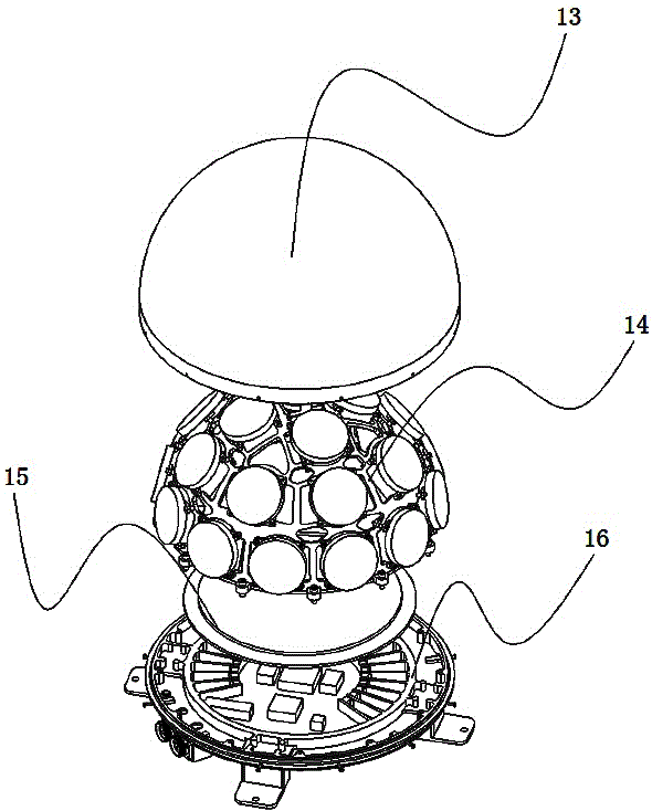
[0039] The structure of this embodiment is basically the same as that of Embodiment 1, the only difference is that the structure of the supporting device is different, such as figure 2 , Figure 8 with Figure 9 As shown, the support device is an L-shaped mount 21, and there are multiple L-shaped mounts 21, which are evenly distributed on the lower surface of the bottom plate 16. Further, the L-shaped mount 21 A stepped hole connected to the bottom plate 16 and a through hole for fixing the L-shaped mounting seat 21 are provided. During installation, the L-shaped mounting seat 21 is fixed to realize a stable installation of the conformal spherical antenna array.

[0040] In the above embodiments, different installation accessories can be installed according to different usage environments to realize the installation and use of vehicles, ships and ground fortifications.


PUM


Abstract

The invention discloses a conformal spherical antenna array which comprises a radome, an antenna array, a shield cover, a base plate and a supporting device. The antenna array is arranged on the base plate. The shield cover is located between the antenna array and the base plate. The antenna array is covered by the radome. The base plate is provided with an annular groove. The lower edge of the radome is inserted into the annular groove and is positioned by a locking positioning mechanism. The supporting device is arranged at the bottom of the base plate. The antenna array comprises a first skeleton, a second skeleton, a third skeleton and an antenna. The first skeleton, the second skeleton and the third skeleton are all arranged within the same ellipsoidal plane. The inclination angle of each skeleton is different. The first skeleton and the second skeleton are tangent to the ellipsoidal plane. The sphere tangent lines of the third skeleton and the second skeleton form a tangent angle a. The conformal spherical antenna array provided by the invention has the advantages of high antenna radiation uniformity, low production cost and stable structure.

Description

technical field [0001] The invention relates to a conformal antenna array, in particular to a conformal spherical antenna array. Background technique [0002] The conformal (ellipse) spherical antenna array can realize omni-directional radiation on the hemispherical surface. It has incomparable advantages in many antenna systems. It can be used in ground communication systems, airborne and vehicle-mounted mobile communication systems, and can also be used in radar, positioning, and navigation fields. [0003] There are many types of conformal antenna arrays, such as conical arrays, spherical arrays, and cylindrical arrays. It has the characteristics of a regular planar antenna array, but also has many differences. [0004] The planar array has been very maturely used in many fields, but its scanning angle is generally up to about 60°. The spherical array can cover all directions. This works well in areas like satellite tracking, communications, etc. Under the condition...

Claims


Application Information

Patent Timeline
Patent Type & Authority Applications(China)
IPC IPC(8): H01Q21/06H01Q1/12
CPCH01Q1/38H01Q1/42H01Q21/06H01Q1/12
Inventor 燕标兰伟吴亚飞
Owner 成都泰格微电子研究所有限责任公司
Why Eureka
Try Eureka