Multi-virtual synchronous generator parallel network control method based on inverter

A technology of virtual synchronization and parallel networking, which is applied in the direction of circuit devices, AC network circuits, and single-network parallel feeding arrangement, etc. Issues such as inertia and damping are not considered, so as to improve the performance of parallel networking, improve safety and reliability, and facilitate hardware implementation

Inactive Publication Date: 2016-10-12
XI AN JIAOTONG UNIV
View PDF1 Cites 23 Cited by
  • Summary
  • Abstract
  • Description
  • Claims
  • Application Information

AI Technical Summary

Problems solved by technology

[0006] The existing droop control only simulates the droop characteristics of synchronous generators, and does not consider the characteristics of large mechanical inertia and large output impedance of synchronous generators, and these characteristics are the reliable parallel networking of synchronous generators and the stable operation of the power grid. indispensable condition
Moreover, inertia and damping are not considered in the mathematical model of the droop method, so when it is applied to the parallel connection of inverters in the microgrid, it may bring a large transient current impact
[0007] At the same time, the design of the droop coefficient is also relatively complicated. Improper design may lead to unstable operation of the inverter and pose a threat to the safe and stable operation of the power grid.

Method used


Image

  • Multi-virtual synchronous generator parallel network control method based on inverter
  • Multi-virtual synchronous generator parallel network control method based on inverter
  • Multi-virtual synchronous generator parallel network control method based on inverter

Examples


Embodiment Construction

[0046] The present invention will be described in further detail below in conjunction with the accompanying drawings.

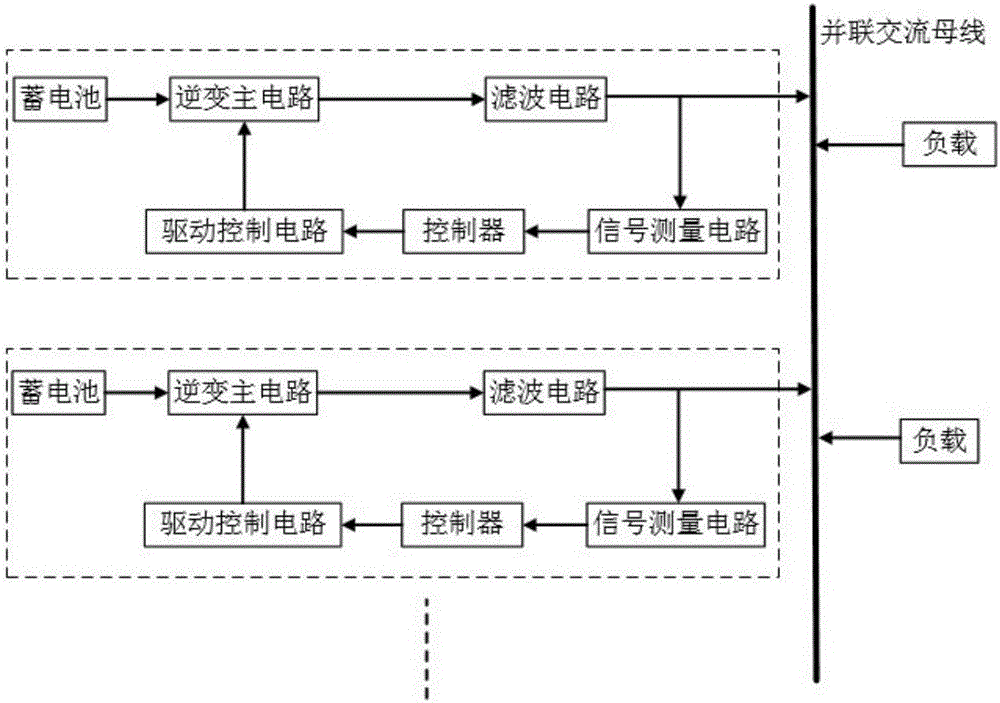
[0047] see image 3 , where each dashed box represents a virtual synchronous generator. Multiple virtual synchronous generators are independently controlled, automatically adjust their output according to the power consumption of the load, and then connect the output of each virtual synchronous generator in parallel to form a microgrid, thereby jointly supplying power to the load. Because the structure of each parallel virtual synchronous generator is the same, the research on the parallel technology of the microgrid system can be realized by studying a single virtual synchronous generator.

[0048] The circuit structure of a single virtual synchronous generator is as follows Figure 4 As shown, the inverter main circuit is a single-phase full-bridge voltage type inverter circuit. The filter circuit adopts an LCL filter circuit, and the drive control circu...


PUM


Abstract

The invention relates to a multi-virtual synchronous generator parallel network control method based on inverters. The method comprises a step of collecting the output voltage u0 and output i0 of a single inverter in a parallel network, obtaining the amplitude U0 and frequency f of parallel network voltage, a step of obtaining the output reactive power Q of the inverter through reactive power and active power calculation, a step of taking U0 and Q as the input of a reactive-voltage control link, and obtaining an excitation EMF E, a step of taking rated active Pref and f as the input of an active-frequency control link, and obtaining a mechanical power Pm, a step of establishing the body model of a virtual synchronous generator, a step of inputting the mechanical power Pm and the excitation EMF E into the synchronous generator model and outputting modulation voltage, and a step of carrying out pulse width modulation on the modulation voltage, carrying out isolation amplification on the modulation voltage to act on an inverter main circuit, and completing the multi-virtual synchronous generator parallel network control based on inverters. According to the invention, the voltage waveform outputted by each inverter in a micro grid can be kept to be consistent, thus the circulating current is suppressed, and the parallel operation of the inverters in the micro grid is realized.

Description

【Technical field】 [0001] The invention relates to the field of micro-grid control, in particular to an inverter-based control method for parallel networking of multiple virtual synchronous generators. 【Background technique】 [0002] With the adjustment of the national economic structure and the rapid development of the power industry, the society has higher and higher requirements for energy utilization, power quality, and power supply safety and reliability. Traditional thermal power generation consumes a large amount of coal-based fossil energy, and the resulting energy shortage, environmental pollution, and greenhouse effect are becoming more and more serious. It is imminent to vigorously promote distributed power generation based on new energy. However, the cost of connecting a single unit of a distributed generation system to the grid is high, control is difficult, and it will have a great impact on the grid. The micro-grid composed of distributed generation units in p...

Claims


Application Information

Patent Timeline
Patent Type & Authority Applications(China)
IPC IPC(8): H02J3/46
CPCH02J3/46H02J2203/20
Inventor 王孙安张磊张滕张斌权盛万兴
Owner XI AN JIAOTONG UNIV
Why Eureka
Try Eureka