
Self-adaptive duty cycle detection and adjustment receiver and control method thereof

A technology of adaptive duty ratio and control method, which is applied in the direction of pulse generation, electrical components, and electric pulse generation, and can solve signal duty ratio deviation, system function failure, input signal duty ratio deviation that cannot be corrected and adjusted, etc. question

Active Publication Date: 2016-10-12
XI AN UNIIC SEMICON CO LTD
View PDF3 Cites 5 Cited by
  • Summary
  • Abstract
  • Description
  • Claims
  • Application Information

AI Technical Summary

Problems solved by technology

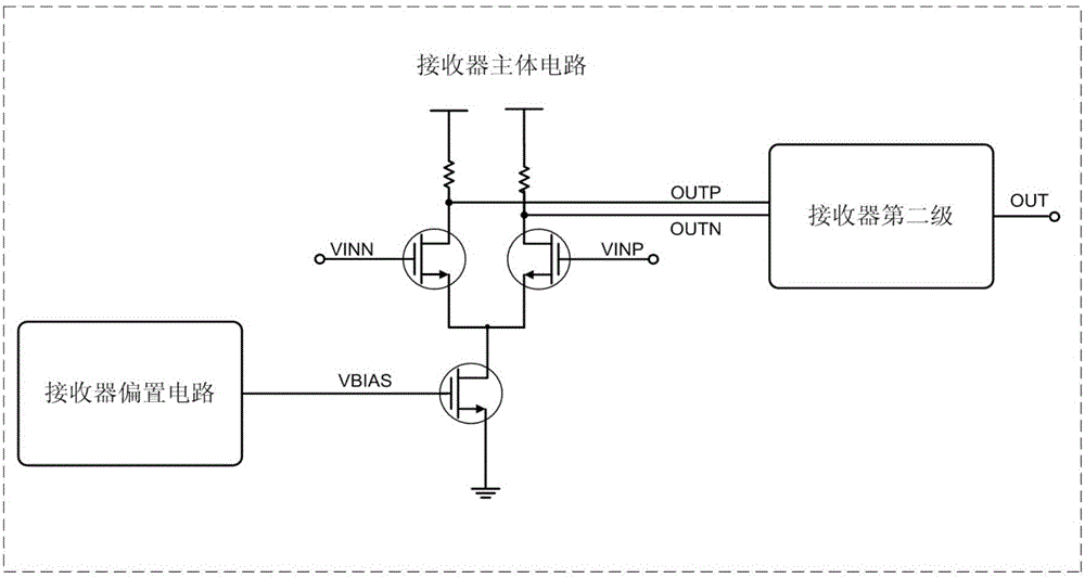
The existing receiver structure can normally receive the input signal, but the deviation of the duty cycle of the input signal cannot be corrected and adjusted
And when there is a mismatch between the bias circuit of the receiver and the main circuit of the receiver, the receiver itself will also introduce a signal duty cycle deviation, which will make the duty cycle of the output signal worse, and the receiver itself cannot detect this. changes, so the receiver cannot be adjusted, resulting in serious problems with the receiver output signal duty cycle
The deterioration of signal integrity will directly affect the function of subsequent signal processing and the effective time window of data. In more serious cases, it will lead to system function failure (setup / hold fail, pulse fail) and chip yield during mass production, especially in In high data rate DDR4 / LPDDR4, the clock frequency is above 2GHz

Method used


Image

  • Self-adaptive duty cycle detection and adjustment receiver and control method thereof
  • Self-adaptive duty cycle detection and adjustment receiver and control method thereof
  • Self-adaptive duty cycle detection and adjustment receiver and control method thereof

Examples


Embodiment Construction

[0035] The present invention will be further described in detail below in conjunction with specific embodiments, which are to explain rather than limit the present invention.

[0036] The invention solves the problem of signal integrity restoration of the input signal in the receiver (Receiver), and provides a detection and adjustment circuit and method for correcting the duty ratio of the DRAM input signal.

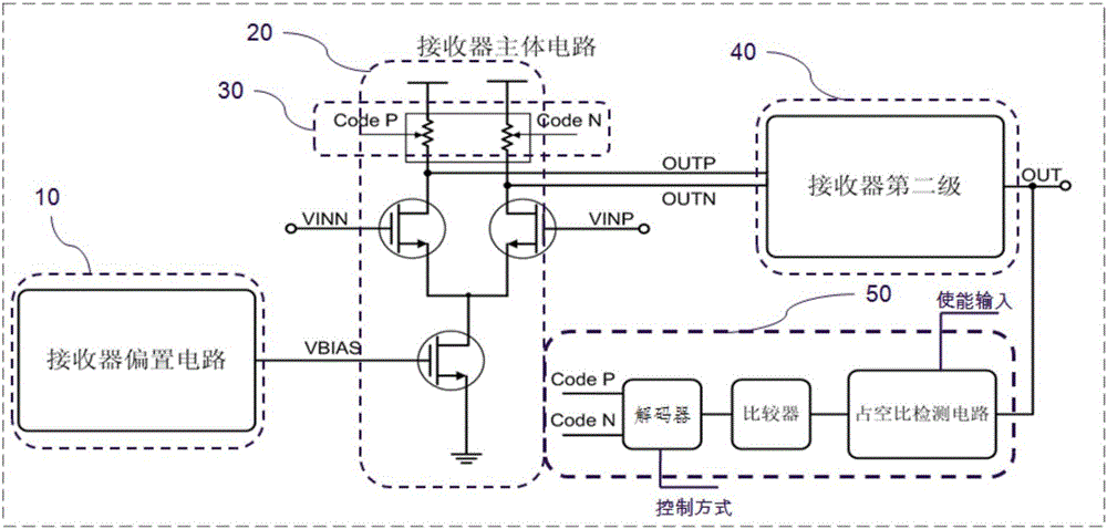
[0037] The present invention is an adaptive duty cycle detection and adjustment receiver, such as figure 2As shown, it at least includes a bias circuit 10, a first-stage amplifier circuit 20, a second-stage amplifier circuit 40 and a duty cycle dynamic detection circuit 50; the load resistance in the first-stage discharge circuit 20 is set as a load resistance array 30;

[0038] The bias circuit 10 is connected to the first-stage amplifying circuit 20 and the second-stage amplifying circuit 40 of the receiver by the bias voltage signal generated by the on-chip active ci...


PUM


Abstract

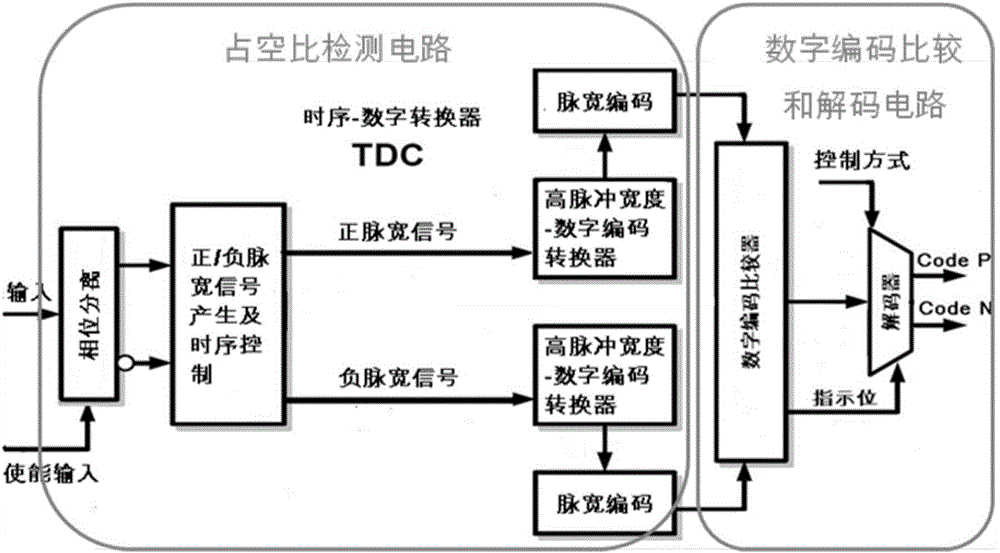
The invention discloses a self-adaptive duty cycle detection and adjustment receiver and a control method thereof. The duty cycle problem of output signals of the receiver can be eliminated. The receiver comprises a bias circuit, a first stage amplifier circuit, a second stage amplifier circuit and a duty cycle dynamic detection circuit which are connected in sequence. The first stage amplifier circuit comprises a bias transistor, input geminate transistors and a load resistor array which are connected in sequence. The gate of the bias transistor is connected with the bias circuit. The load resistor array comprises a master load resistor which is always connected with the drain ends of the input geminate transistors, and a programmable resistor array which is selectively connected with the drain ends of the input geminate transistors. The duty cycle dynamic detection circuit comprises a duty cycle detection circuit, a digital encoding comparer and a decoder which are connected in sequence. Two output ways of the decoder are connected with the programmable resistor array through adoption of forward encoding and reverse encoding control codes. The forward encoding and reverse encoding control codes control access or short circuit of the programmable load resistor array on the two drain ends of the input geminate transistors.

Description

technical field [0001] The invention relates to a duty ratio adjustment technology applied to a dynamic random access memory receiver, in particular to an adaptive duty cycle detection and adjustment receiver and a control method thereof. Background technique [0002] DRAM (Dynamic Random Access Memory), namely dynamic random access memory, is the most common system memory. DRAM can only hold data for a short period of time. In order to keep data, DRAM uses capacitors for storage, so it must be refreshed at regular intervals. If the memory cells are not refreshed, the stored information will be lost. However, the leakage phenomenon of capacitors is inevitable. If the charge is insufficient, data errors will occur. Therefore, the capacitors must be periodically refreshed (pre-charged), which is also a major feature of DRAM. Moreover, the charging and discharging of capacitors requires a process, and the refresh frequency cannot be increased indefinitely (frequency barrier),...

Claims


Application Information

Patent Timeline
Patent Type & Authority Applications(China)
IPC IPC(8): H03K3/017
CPCH03K3/017
Inventor 卫秦啸
Owner XI AN UNIIC SEMICON CO LTD
Learn More