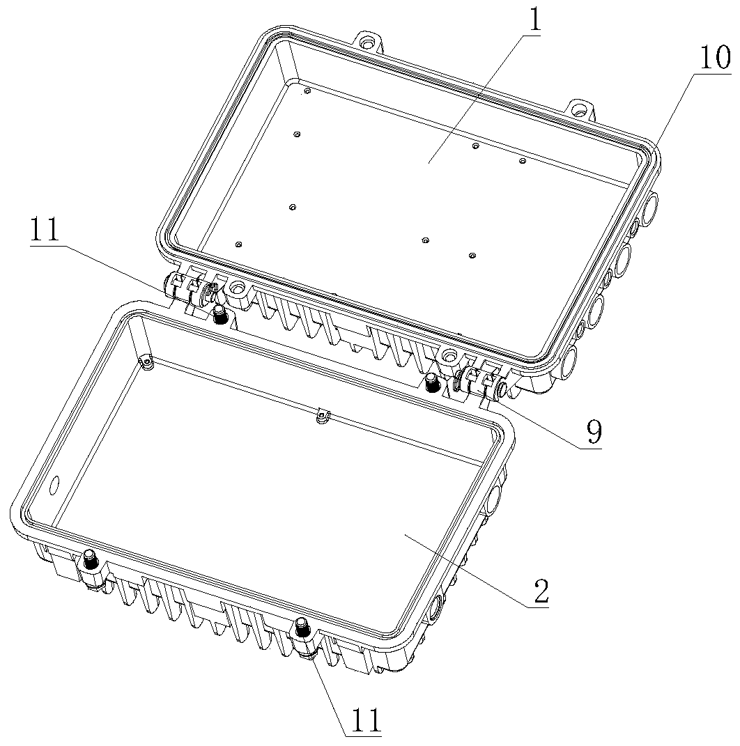
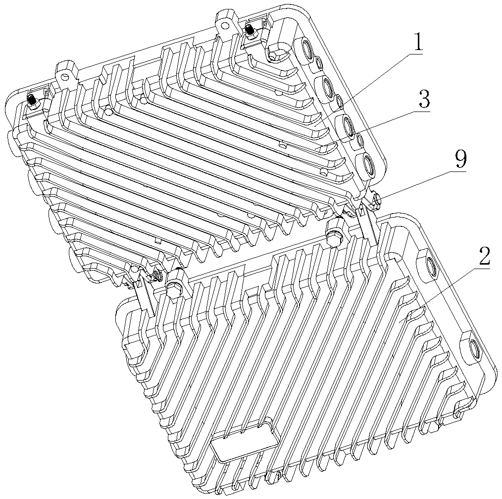
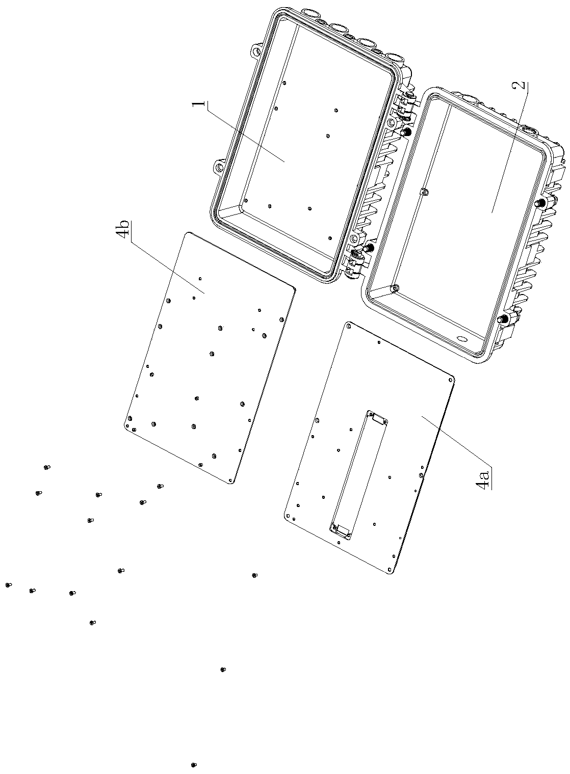
An outdoor optical network platform
A network platform and field optical technology, applied in the field of field optical network platform, to achieve reasonable heat dissipation structure, strong adaptability to the use environment, and increase the effect of heat dissipation contact area
- Summary
- Abstract
- Description
- Claims
- Application Information
AI Technical Summary
Problems solved by technology
Method used
Image
Examples
specific Embodiment 1
[0073] Specific embodiment 1: see Figure 14 , two OLT input optical fibers 14 and EDFA input optical fibers 15 are connected to the field optical network platform through the same waterproof connector 13b on the bottom shell 1 of the housing, and the two OLT input optical fibers 14 are respectively connected to two Uplink GE port 76, two-way OLT input optical fiber 14 is connected to OLT connection board 74 through uplink GE port 76, four-way OLT output fiber 16 is connected from the waterproof connector 13e on the bottom shell 1 of the housing, and four-way OLT output fiber 16 Connect the downlink PON port 79 respectively after the fiber reels 8, and the four-way OLT output optical fiber 16 is connected to the OLT connection plate 74 through the downlink PON port 79, so that the OLT input optical fiber 14 is connected with the OLT output optical fiber 16, so that the OLT input optical fiber 14 and the OLT output optical fiber 16 are connected to the OLT module 7, and the wat...
specific Embodiment 2
[0076] Specific embodiment 2: see Figure 15 , two OLT input optical fibers 14 are connected to the field optical network platform through the waterproof connector 13b on the housing bottom shell 1, and the two OLT input optical fibers 14 are respectively connected to two uplink GE ports 76 after passing through the fiber wheel 8. The OLT input optical fiber 14 is connected to the OLT connection board 74 through the uplink GE port 76, the four OLT output optical fibers 16 are connected through the waterproof connector 13e on the bottom shell 1 of the housing, and the four OLT output optical fibers 16 are connected through the fiber wheel 8. Then respectively connect the downstream PON port 79, and the four OLT output optical fibers 16 are connected to the OLT connection board 74 through the downstream PON port 79, so that the OLT input optical fiber 14 is connected with the OLT output optical fiber 16, thereby connecting the OLT input optical fiber 14 with the OLT output optica...
specific Embodiment 3
[0079] Specific embodiment 3: see Figure 16, two OLT input optical fibers 14 are connected to the field optical network platform from the waterproof connector 13b on the housing bottom shell 1, and the two OLT input optical fibers 14 are respectively connected to the uplink GE port 76 after passing through the fiber wheel 8. The input optical fiber 14 is connected to the OLT connection board 74 through the uplink GE port 76, and the four-way OLT output optical fiber 16 is connected through the waterproof connector 13e on the bottom shell 1 of the housing. Connect the downlink PON port 79, the four-way OLT output optical fiber 16 is connected to the OLT connection board 74 through the downlink PON port 79, so that the OLT input optical fiber 14 is connected to the OLT output optical fiber 16, and the waterproof connector 13d and the waterproof connector 13c are spare interfaces for the OLT output optical fiber 16 ;
[0080] The EDFA input optical fiber 15 and the EDFA output ...
PUM
 Abstract
Description
Claims
Application Information
 - R&D
- Intellectual Property
- Life Sciences
- Materials
- Tech Scout
- Unparalleled Data Quality
- Higher Quality Content
- 60% Fewer Hallucinations
Browse by: Latest US Patents, China's latest patents, Technical Efficacy Thesaurus, Application Domain, Technology Topic, Popular Technical Reports.
© 2025 PatSnap. All rights reserved.Legal|Privacy policy|Modern Slavery Act Transparency Statement|Sitemap|About US| Contact US: help@patsnap.com


