Laser welding method
A laser welding and laser technology, applied in laser welding equipment, welding equipment, metal processing equipment and other directions, can solve the problem of reducing the strength of the welding part, achieve a good welding state, and inhibit the effect of air bubbles
- Summary
- Abstract
- Description
- Claims
- Application Information
AI Technical Summary
Problems solved by technology
Method used
Image
Examples
Embodiment approach
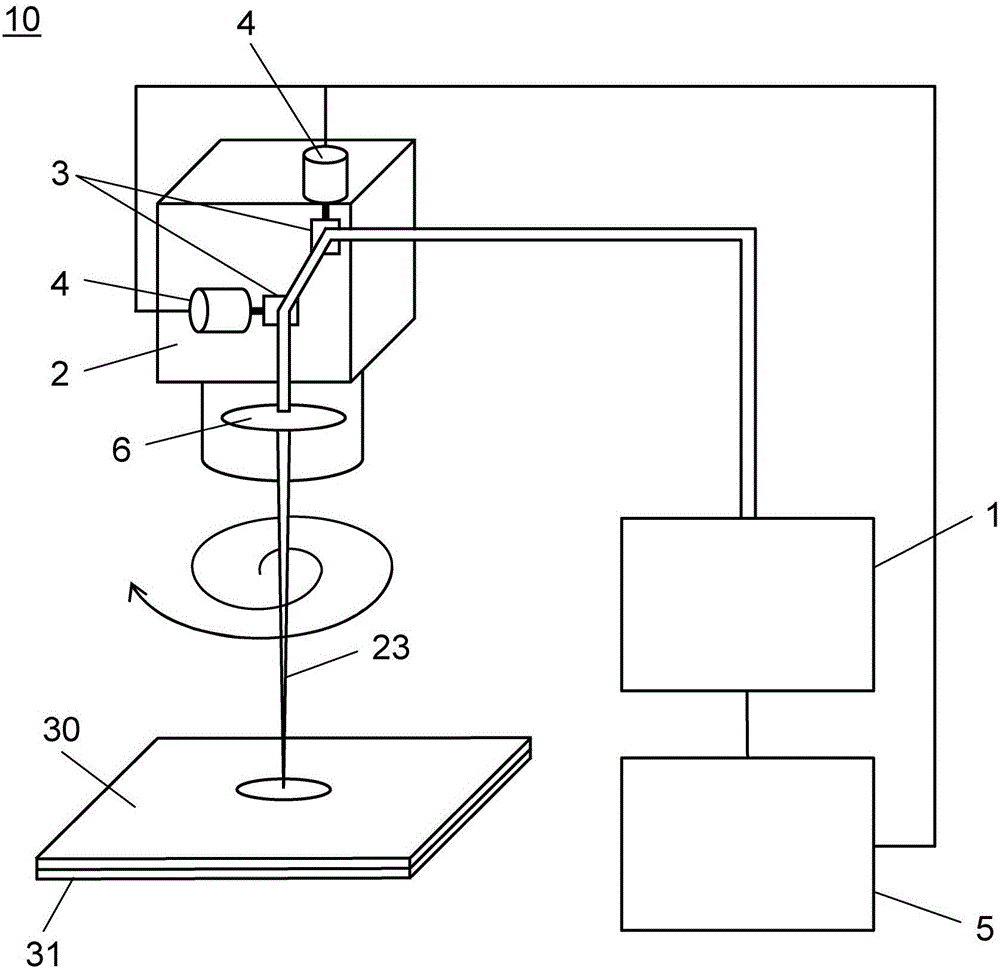
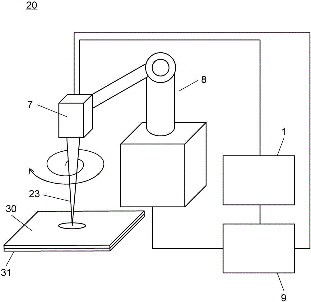
[0029] use Figure 1 to Figure 14 This embodiment will be described.
[0030] First, use figure 1 and figure 2 The laser welding system for carrying out the laser welding method of this embodiment is demonstrated. It should be noted, figure 1 It is the laser welding system 10 using the galvano scanner (Galvano Scanner) 2 of this embodiment. figure 2 It is the laser welding system 20 using the robot 8 of this embodiment.
[0031] exist figure 1 Among them, the laser welding system 10 has a laser oscillator 1 , a galvanometer scanner 2 and a scanner control device 5 . The laser oscillator 1 generates laser light 23 . The vibrating mirror scanner 2 has two vibrating mirrors 3 , two vibrating mirror motors 4 , and an Fθ lens 6 . The vibrating mirror 3 two-dimensionally changes the trajectory of the laser beam 23 . The two vibrating mirror motors 4 rotate the respectively connected vibrating mirrors 3 . In addition, the two vibrating mirror motors 4 are controlled by a ...
Embodiment 1
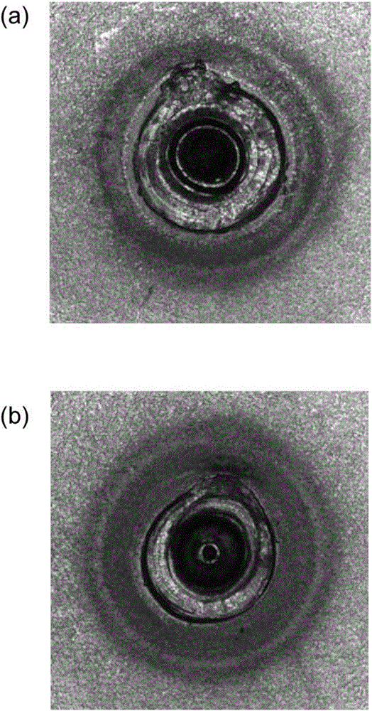
[0056] Below, with respect to comparative example 1 and comparative example 2, utilize Figures 9 to 11 Example 1 for carrying out the present invention will be described. Figure 9 The results of laser welding in this example are shown, (a) is a plan view of the upper surface, and (b) is a plan view of the lower surface. Figure 10 It is a sectional view showing the principle of laser welding in this embodiment. Figure 11 The state of the laser welding of this Example is shown, (a) is a top view, (b) is a cross-sectional view. It should be noted that sometimes for Figure 3-5 The same structures are assigned the same reference numerals, and descriptions thereof are omitted.
[0057] Figure 9 Shows the welding state (processing result) of the upper surface and the lower surface of the workpiece when the laser welding of the spiral orbit is performed on the overlapped workpiece under the third welding condition, (a) is a plan view of the upper surface, (b) ) is the plan ...
Embodiment 2
[0071] Below, use Figure 12 Example 2 for carrying out the present invention will be described. Figure 12 It is a plan view showing the state of laser welding in this embodiment. It should be noted that, for Figure 11 The same reference numerals are used for the same structures in (a), and description thereof will be omitted.
[0072] As for the spiral track 51 of the laser beam 23 , if the adjacent tracks 51 are at equal intervals, the temperature is higher at a portion closer to the center of the melting pool 22 . Therefore, the molten pool 22 tends to be enlarged, and the laser beam 23 is easily irradiated to the molten pool 22 . In order to avoid this situation, the laser welding method of the present embodiment such as Figure 13 As shown, when welding is performed by irradiating the laser beam 23 spirally from the inner side toward the outer side, the irradiation start position at which the laser beam 23 is irradiated spirally is set as the second starting point 5...
PUM
| Property | Measurement | Unit |
|---|---|---|
| diameter | aaaaa | aaaaa |
Abstract
Description
Claims
Application Information
 - R&D
- Intellectual Property
- Life Sciences
- Materials
- Tech Scout
- Unparalleled Data Quality
- Higher Quality Content
- 60% Fewer Hallucinations
Browse by: Latest US Patents, China's latest patents, Technical Efficacy Thesaurus, Application Domain, Technology Topic, Popular Technical Reports.
© 2025 PatSnap. All rights reserved.Legal|Privacy policy|Modern Slavery Act Transparency Statement|Sitemap|About US| Contact US: help@patsnap.com


