Exhaust gas post treatment system

An exhaust gas post-treatment and exhaust gas technology, which is applied in exhaust gas treatment, exhaust devices, mechanical equipment, etc., can solve the problems of passive regeneration of unaided filter matrix, large heat loss, etc., to reduce the total mass and improve the starting performance. , the effect of reducing heat capacity

Inactive Publication Date: 2016-10-12
ROBERT BOSCH GMBH
View PDF8 Cites 13 Cited by
  • Summary
  • Abstract
  • Description
  • Claims
  • Application Information

AI Technical Summary

Problems solved by technology

The heat losses associated with this are large
Apart from this, this system does not facilitate the passive regeneration of the filter matrix

Method used


Image

  • Exhaust gas post treatment system
  • Exhaust gas post treatment system
  • Exhaust gas post treatment system

Examples


Embodiment Construction

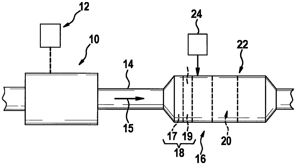
[0041] exist figure 1 The internal combustion engine is marked with the reference numeral 10 in FIG. 2 , which is controlled by a schematically shown control unit 12 via signal lines. Exhaust gases are discharged via an exhaust line 14 along a flow path 15 in which an exhaust gas aftertreatment system 16 is arranged. Exhaust gas aftertreatment system 16 is included in figure 1 Only the particle filter 17 and the device 19 with catalytic oxidation function are shown in a simplified manner, which can be combined to form a particle filter 18 with catalytic oxidation function.

[0042] At least one mixing chamber 20 can also be combined with the particle filter 18 with catalytic oxidation function to form a structural unit 22 . On the one hand, particles can be filtered out of the exhaust gas flowing in the exhaust pipe 14 by means of the catalytic particle filter 18 and can also be activated at the catalytic converter integrated in the catalytic particle filter 18 Catalytic ox...


PUM


Abstract

The invention relates to an exhaust gas post-treatment system (16) for purifying exhaust gas from an internal combustion engine (10) and to a corresponding method. Said system is characterised in that a particle filter (17), a device with a catalytic oxidation function (19) and at least one mixing chamber (20) are combined to form a structural unit (22).

Description

technical field [0001] The invention relates to an exhaust gas aftertreatment system for purifying the exhaust gas of an internal combustion engine, which comprises a particle filter with catalytic oxidation function and at least one mixing chamber (they are combined to form a structural unit), and also relates to a Corresponding methods for exhaust gas aftertreatment. Background technique [0002] Internal combustion engines, especially diesel-powered motor vehicles, emit a complex mixture of air pollutants including particulates or particulates as well as gaseous compounds, especially nitrogen oxides (NO x ), carbon monoxide (CO) and unburned hydrocarbons (HC). As existing exhaust emission standards become more and more stringent, efforts are made to regulate the amount of air pollutants emitted by internal combustion engines. [0003] In the exhaust gas aftertreatment system, in addition to the oxidation catalyst and the soot filter, the selective catalytic reduction me...

Claims


Application Information

Patent Timeline
Patent Type & Authority Applications(China)
IPC IPC(8): F01N3/28F01N3/033F01N3/035F01N13/00F01N3/10F01N3/20F01N13/18F01N3/021
CPCF01N3/106F01N3/2066F01N3/2892F01N13/1888F01N3/021F01N2240/20F01N2250/02F01N2570/14F01N2610/02F01N2900/0416F01N2900/1402F01N2900/1404F01N2900/1406F01N2900/1411F01N13/009Y02T10/12F01N13/0097F01N3/035F01N3/103F01N3/2882F01N2610/01
Inventor H·布雷斯勒C·奥塞曼C·贝克尔
Owner ROBERT BOSCH GMBH
Why Eureka
Try Eureka