Air-cooled engine and engine working machine

An engine, air-cooled technology, used in engine components, engine cooling, machine/engine, etc., to solve problems such as appearance defects, ablation, deformation, etc.

Active Publication Date: 2016-10-12
KOKI HLDG CO LTD
View PDF8 Cites 4 Cited by
  • Summary
  • Abstract
  • Description
  • Claims
  • Application Information

AI Technical Summary

Problems solved by technology

Therefore, the muffler cover 136 is likely to be thermally damaged, such as ablation due to receiving radiant heat from the muffler and heat of natural convection.
In particular, in areas visible from the outside, thermal damage such as burns, discoloration, and deformation causes defects in appearance, so there is a problem that product value deteriorates significantly

Method used


Image

  • Air-cooled engine and engine working machine
  • Air-cooled engine and engine working machine
  • Air-cooled engine and engine working machine

Examples


Embodiment Construction

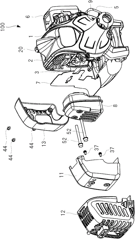
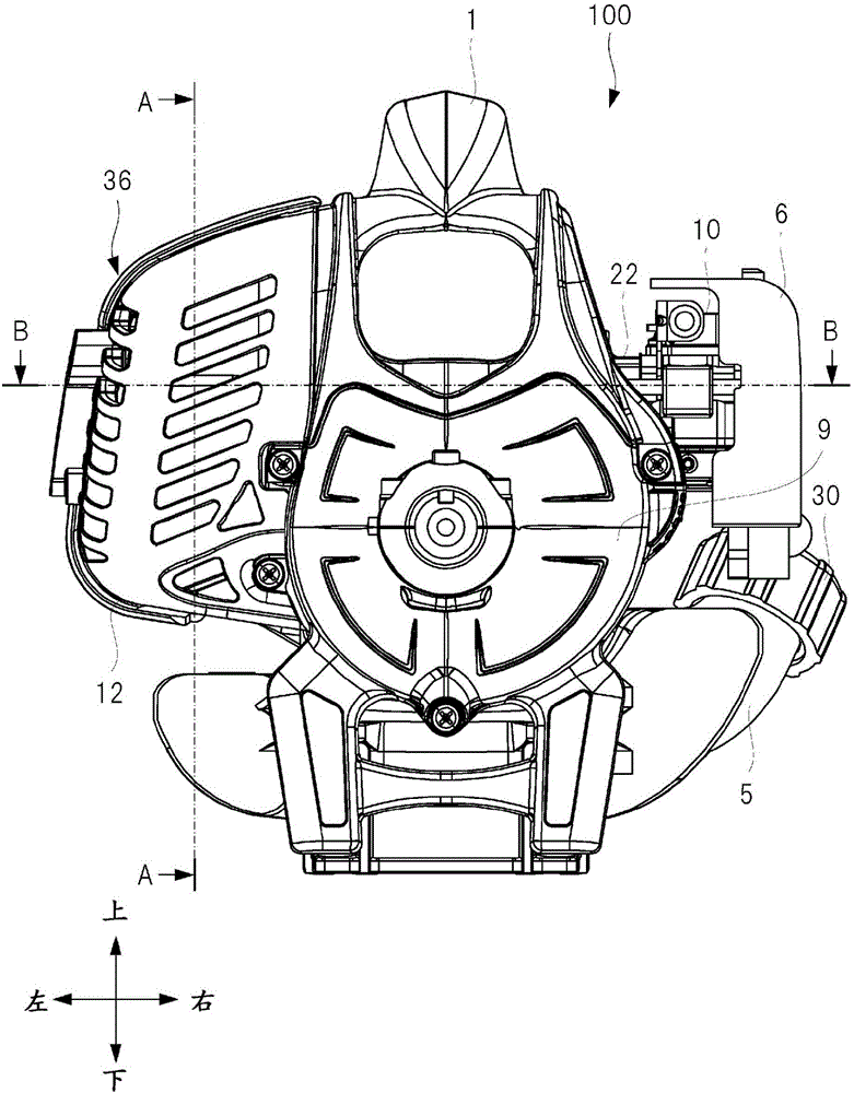
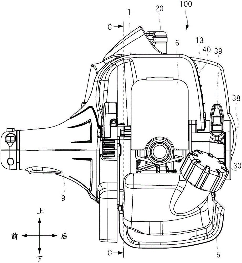
[0026] The structure of an air-cooled engine (engine) as an embodiment of the present invention will be described. Herein, the air-cooled engine includes a two-stroke engine main body having a cylinder block, a crankcase, and the like, and a block head that covers the cylinder block and the like. In the engine main body, a cooling fan is fixed to the drive shaft, and the cylinder block is cooled in the block head by cooling air generated by the rotation of the cooling fan. Further, in the cylinder, a plurality of cooling fins are formed on the outer surface of the cylinder portion formed in a substantially cylindrical shape, and the combustion chamber is formed inside the cylinder portion.

[0027] This engine is suitable for a portable work machine carried by an operator, such as a brush cutter and a blower, and the engine having the above structure is installed in the engine work machine. Therefore, actually, a speed reducer, etc. for driving the engine working machine are ...


PUM


Abstract

An air-cooled engine includes a muffler (8) that is attached to an exhaust port of a cylinder (2) and a fan case (9) that houses a cooling fan (18), and a cylinder cooling room (34) is formed by a cylinder cover that houses the cylinder (2). A muffler cooling room (35) is formed by a first muffler cover (11) that covers at least some of the muffler (8) through a clearance and a second muffler cover (12) that covers at least some of the first muffler cover (11) through a clearance. Some of cooling air generated by the cooling fan (18) is supplied to the muffler cooling room (35). The cooling air is supplied to at least one of a first space (32A) between the muffler (8) and the first muffler cover (11) and a second space (32B) between the first muffler cover (11) and the second muffler cover (12).

Description

technical field [0001] The invention relates generally to air-cooled engines used as power sources for portable work machines such as bush cutters and blowers, work machines such as generators, and in particular to air-cooled engine cooling structure. Background technique [0002] Small air-cooled engines are widely used as power sources for small work machines such as bush cutters and chain saws. Figure 11 It is a perspective view showing a schematic diagram of a brush cutter 101 as an example of an engine working machine. like Figure 11 As shown, a small air-cooled engine 110 is installed in an engine working machine. The engine working machine includes a hollow main body 105 , and an engine 110 is provided at one end of the main body 105 , and a rotary blade 106 is provided at the other end of the main body 105 . A drive shaft (not shown) is configured inside the main tube body 105 . By rotating the drive shaft by the motor 110 , the rotary blade 106 is rotated. Nea...

Claims


Application Information

Patent Timeline
Patent Type & Authority Applications(China)
IPC IPC(8): F01P1/06F01N3/10F01N13/00F01N13/14F01N1/14
CPCF01N1/14F01N3/10F01N13/002F01N13/14F01N13/141F01N13/143F01N2230/04F01N2260/022F01N2260/20F01N2590/06F01P1/06F01P1/02F01P5/04F01P2001/023F02B63/02F02B75/02F02B2075/025
Inventor 一桥直人川口健文久下沼淳
Owner KOKI HLDG CO LTD
Why Eureka
Try Eureka