A water-cooled layered cooling mold and its application

A mold and layer technology, applied in the field of casting molds, can solve the problems of no cooling scheme, energy waste, high equipment requirements, etc., and achieve the effect of rapid cooling

Active Publication Date: 2019-04-23
FOSHAN NANHAI SUPERBAND MOLD
View PDF6 Cites 0 Cited by
  • Summary
  • Abstract
  • Description
  • Claims
  • Application Information

AI Technical Summary

Problems solved by technology

Some mold manufacturers use point-cooled or line-cooled water-cooled structures. This structure has a significant effect on the local area, and has little effect on structural parts with large-area high-performance requirements. Moreover, the line-cooled structure is easy to be in the waterway after the cooling stops. Water accumulation is formed in the middle, and compressed air needs to be introduced to discharge the excess water, which requires high equipment and causes waste of energy for the cooling part.
For castings with large area and high strength requirements such as hubs and rims, there is currently no perfect cooling solution

Method used


Image

  • A water-cooled layered cooling mold and its application

Examples


Embodiment Construction

[0015] The present invention will be further described below in conjunction with the accompanying drawings and specific embodiments.

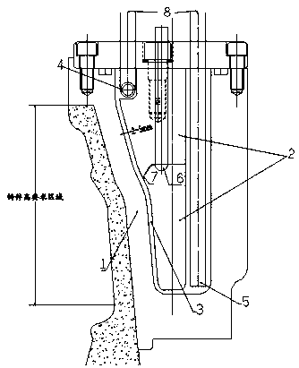
[0016] As shown in the figure, the present invention provides a water-cooled layered cooling mold, which includes a casting mold (1) and a water cavity insert (2), and is characterized in that: the casting mold (1) and the water cavity insert (2) ) to form an accompanying cooling cavity (3), the top of the cooling cavity (3) is embedded with cloth drill holes to form a linear or circular circle of water pipes (4) that evenly enter the water, and the opening is embedded with a sealing ring and locked with a cover plate Tighten to ensure airtightness. The accompanying cooling cavity formed between the mold (1) and the water chamber insert (2) has a gap of 2-5mm. The lower end of the cooling cavity (3) is provided with a water outlet. The water outlets are more than two outlet pipes (5) extending evenly from the bottom of the cavity. The outlet p...


PUM


Abstract

The invention provides a water-cooling laminated surface cold mold. The water-cooling laminated surface cold mold comprises a casting mold (1) and a water cavity insert (2), wherein a servo cooling cavity (3) is formed between the casting mold (1) and the water cavity insert (2), the top end of the cooling cavity (3) is embedded in a drill hole to form a circle of linear or round water pipe (4) allowing uniform water inflow, and the open portion is embedded in a sealing ring and locked with a cover plate to guarantee airtightness. The cooling cavity is divided into two or more layers, a water outlet channel and a water inlet are formed in the split portion, and then the water channel is connected with a water source pipe outside the mold through a borehole. According to the water-cooling laminated surface cold mold, cooling is quick, cylindrical surface or large plane high-performance requirements for products can be met by means of the surface cooling scheme, the temperature of the mold can be controlled easily through laminated cooling, and proper temperature can guarantee high quality and high performance of castings. Furthermore, redundant water accumulated at the bottom of the cavity can be discharged quickly after cooling is finished.

Description

technical field [0001] The invention relates to the technical field of mechanical casting, in particular to a casting mold. Background technique [0002] Metal casting, commonly known as hard mold casting, is a process in which castings are made of metal materials, and molten metal is poured into molds under gravity to obtain castings. Metal casting is not only suitable for mass production of non-ferrous alloy castings such as aluminum alloys and magnesium alloys with complex shapes, but also for the production of iron and steel metal castings and ingots. For example: as one of the most important moving parts of a car, the wheel hub has high requirements for its performance, quality and service life. The wheel hub is generally produced by casting. The mold used for casting mainly includes an upper mold, a lower mold, a side mold and a base. After the combination of the upper mold, the lower mold and the side mold, a casting cavity for casting the wheel hub is formed. Both ...

Claims


Application Information

Patent Timeline
Patent Type & Authority Patents(China)
IPC IPC(8): B22D27/04
CPCB22D27/04
Inventor 李磊
Owner FOSHAN NANHAI SUPERBAND MOLD
Why Eureka
Try Eureka