Robot wheelchair vehicle

A wheelchair and robot technology, which is applied to patient chairs or special transportation tools, vehicle rescue, medical transportation, etc. It can solve the problems of heavy wheelchair operation, single wheelchair function, poor emergency effect, etc., and achieve convenient shipping and carrying. , Simple operation, flexible use of effects

Active Publication Date: 2016-10-26
鄢俊
View PDF4 Cites 15 Cited by
  • Summary
  • Abstract
  • Description
  • Claims
  • Application Information

AI Technical Summary

Problems solved by technology

[0003] The purpose of the present invention is to provide a robot wheelchair vehicle to solve the problems of the existing wheelchairs that rely on crawlers to climb stairs and the complicated operation of functions, and also solve the problems of the existing wheelchairs with single functions and poor emergency response

Method used


Image

  • Robot wheelchair vehicle
  • Robot wheelchair vehicle
  • Robot wheelchair vehicle

Examples


specific Embodiment approach 1

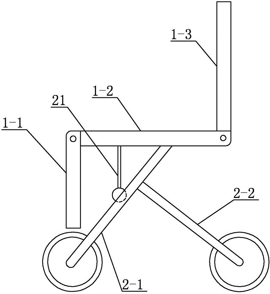
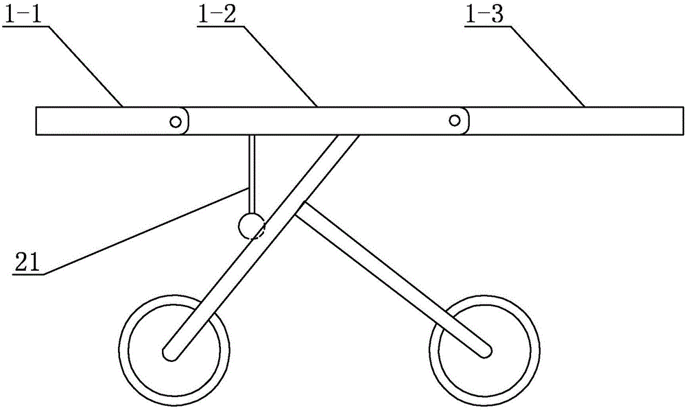
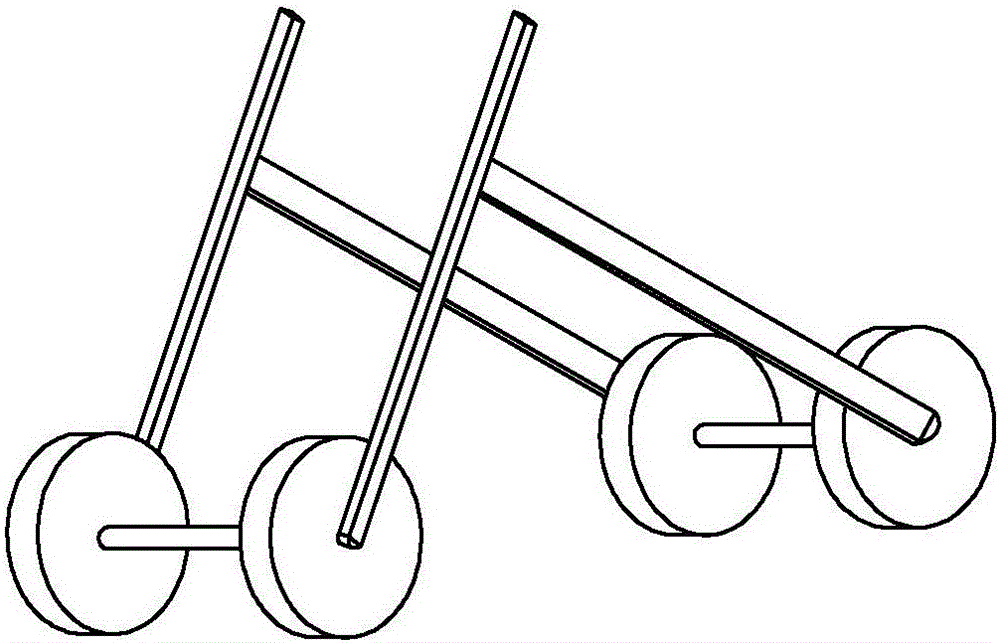
[0041] Specific implementation mode one: combine figure 1 , figure 2 , image 3 , Figure 4 , Figure 5 , Figure 6 , Figure 7 , Figure 8 , Figure 9 , Figure 10 , Figure 11 , Figure 12 , Figure 13 , Figure 14 , Figure 15 , Figure 16 , Figure 17 and Figure 18 Describe this embodiment, which includes a power transmission system, an angle sensing system, a load-bearing deformation system, a leg movement system and four road wheel assemblies;

[0042] The power transmission system includes a power supply, a total motor and two sub-motors 19;

[0043] Described angle sensing system comprises controller, end sensor, angle displacement sensor and four groups of electromagnets 8, and described controller, end sensor, angle displacement sensor and four groups of electromagnets 8 are all connected with power supply, control The controller is connected with the sub-motor 19 respectively; the controller is connected with the end sensor, the angular displaceme...

specific Embodiment approach 2

[0050] Specific implementation mode two: combination figure 1 , figure 2 , image 3 , Figure 4 , Figure 5 , Figure 6 , Figure 7 and Figure 16 Describe this embodiment, in this embodiment, when the ratchet assembly is a straight elastic pawl assembly 4, the pawl assembly is set correspondingly to the electromagnet 8, and the traveling wheel assembly includes a hub 3 and a direct elastic pawl assembly 4. The direct elastic pawl assembly 4 and its corresponding group of electromagnets 8 are all arranged in the hub 3, the direct elastic pawl assembly 4 includes a plurality of direct elastic pawl monomers, and the circumferential end surface of the wheel hub 3 is processed with A plurality of first through-holes 9 that are arranged in one-to-one correspondence with the direct-elastic pawl monomers, and a plurality of direct-elastic pawl monomers are evenly distributed on a corresponding group of electromagnets 8, and each direct-elastic pawl single The body includes a ...

specific Embodiment approach 3

[0051] Specific implementation mode three: combination figure 1 , figure 2 , image 3 , Figure 4 , Figure 8 , Figure 9 and Figure 16 This embodiment is described. In this embodiment, when the pawl assembly is a prostrate pawl assembly 10, the pawl assembly is correspondingly arranged with the electromagnet 8, and the traveling wheel assembly includes a hub 3 and a prostrate pawl assembly 10. The electromagnet 8 corresponding to the prostrate pawl assembly 10 is arranged in the hub 3. The prostrate pawl assembly 10 includes an auxiliary support frame 20 and a plurality of prostrate pawl monomers. A second through hole 11 corresponding to the prostrate pawl monomer one by one, a plurality of crouching pawl monomers are evenly distributed on its corresponding electromagnet 8, each prostrate pawl monomer includes The second spring 12, the second support rod 13 and the second end support block 14, the auxiliary support frame 20 is coaxially arranged with the wheel hub 3,...


PUM


Abstract

The invention discloses a robot wheelchair vehicle, and relates to a wheelchair vehicle. At present, most wheelchairs, which are designed to assist physically disabled patients and people difficult to move in riding instead of walk, are single in function and poor in emergency effect. According to the wheelchair vehicle, a leg moving system is arranged on the lower end face of a seat plate in power; the leg moving system comprises a front leg connecting, a rear leg connecting shaft and two groups of herringbone regulating brackets; a walking wheel assembly is arranged on each front leg rod and a walking wheel assembly is arranged on each rear leg rod; the two walking wheel assemblies on the two front leg rods are connected by virtue of the front leg connecting shaft; the two walking wheel assemblies on the two rear leg rods are connected by virtue of the rear leg connecting shaft; the front leg connecting shaft and the rear leg connecting shaft are rotated by virtue of a power supply; and each pawl can make an action of extending out of a corresponding hub or shrinking into the hub. The robot wheelchair vehicle disclosed by the invention is applicable to medicine and daily lives; in addition, the robot wheelchair vehicle is also provided with image pickup and sensor devices; and the wheelchair, when transformed into a stretcher vehicle, can serve as a rescuing device, a detection vehicle and a scout vehicle; therefore, the wheelchair vehicle achieves multiple purposes.

Description

technical field [0001] The invention relates to a robot wheelchair, which belongs to the technical field of machinery and automation. Background technique [0002] Wheelchair is an important tool for rehabilitation. It is not only a means of transportation for physically disabled and handicapped people, but more importantly, it enables them to perform physical exercises and participate in social activities with the help of wheelchairs. Ordinary wheelchairs are generally composed of four parts: wheelchair frame, wheels, brake device and seat. Most of the wheelchairs currently on the market use crawlers to climb slopes and stairs, which is bulky, cumbersome to operate, and cannot be folded or disassembled, which makes shipment inconvenient. In addition, most of the people who use wheelchairs are physically handicapped and people with limited mobility. Once a situation requiring first aid occurs, the scope of use of the wheelchair is limited because the structure cannot be cha...

Claims


Application Information

Patent Timeline
Patent Type & Authority Applications(China)
IPC IPC(8): A61G5/06A61G5/08A61G5/10
CPCA61G5/061A61G5/08A61G5/10
Inventor 鄢俊崔刚鄢博宇王秀峰
Owner 鄢俊
Why Eureka
Try Eureka