Novel box girder bottom die system

A bottom form and box girder technology, which is applied in ceramic forming machines, auxiliary forming equipment, lifting devices, etc., can solve the problems that the bottom formwork cannot be moved effectively and cannot be directly applied to the construction of ultra-high twisted body segment box girder, etc. The effect of convenient processing and use, shortening construction period and reducing construction strength

Active Publication Date: 2016-10-26
CCCC SECOND HARBOR ENG
View PDF7 Cites 7 Cited by
  • Summary
  • Abstract
  • Description
  • Claims
  • Application Information

AI Technical Summary

Problems solved by technology

However, the bottom formwork disclosed in this utility model cannot be moved effectively, so it cannot be direc

Method used


Image

  • Novel box girder bottom die system
  • Novel box girder bottom die system
  • Novel box girder bottom die system

Examples


Example Embodiment

[0033] In order to make the objectives, technical solutions, and advantages of the present invention clearer, the following further describes the present invention in detail with reference to the accompanying drawings and embodiments. It should be understood that the specific embodiments described here are only used to explain the present invention, but not to limit the present invention.

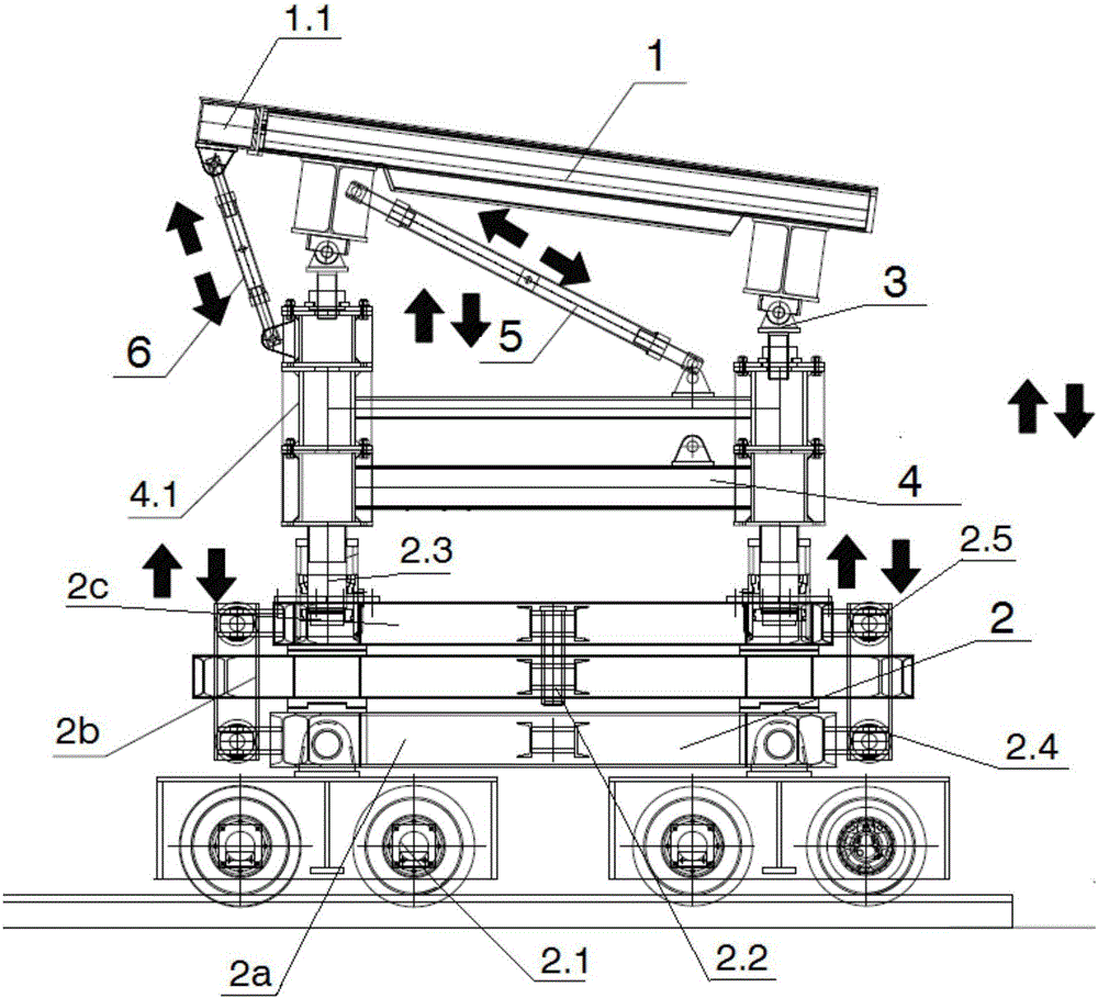
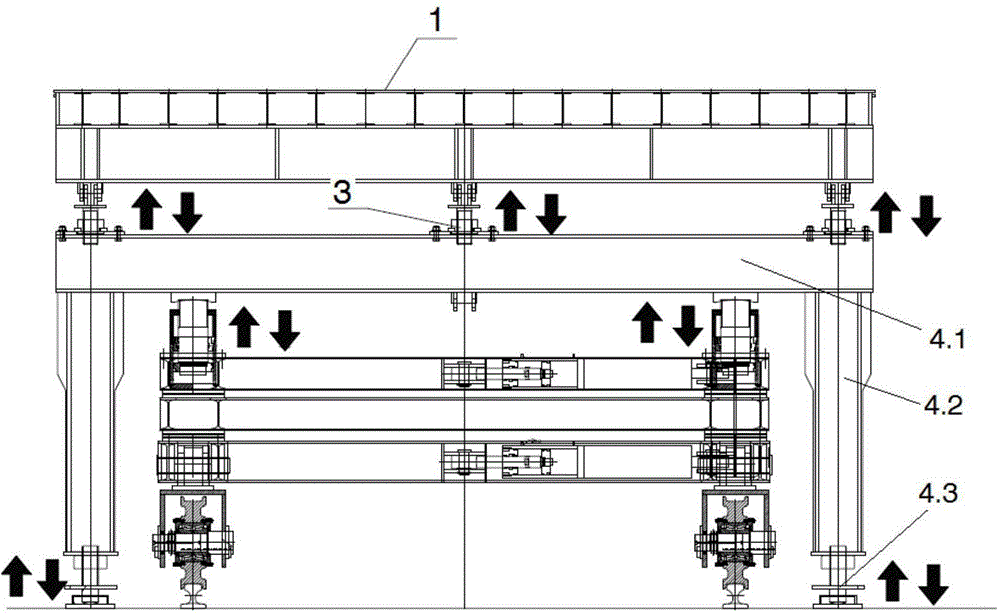
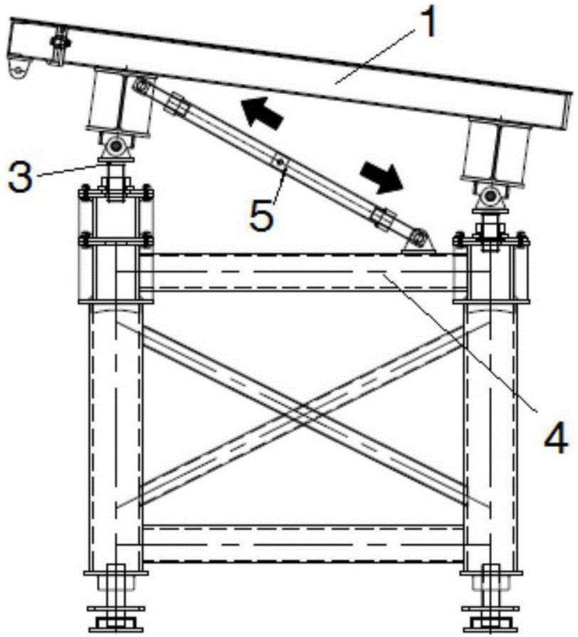
[0034] by Figure 1 to Figure 2 As shown in a new type of box girder bottom mold system, the present invention includes a bottom mold trolley 2 installed on a preset track; the bottom mold trolley 2 is connected with a bottom mold 1; the bottom mold trolley 2 is provided with The hydraulic jacking cylinder 2.3 for lifting the bottom mold, the hydraulic horizontal moving cylinder 2.4 for translating the bottom mold and the hydraulic rotating cylinder 2.5 for rotating the bottom mold; a bottom support 4 is provided between the bottom mold trolley 2 and the bottom mold 1. ; Between the bottom sup...


PUM


Abstract

The invention discloses a novel box girder bottom die system. The novel box girder bottom die system comprises a bottom die trolley installed on a preset rail. A bottom die is connected to the bottom die trolley. A hydraulic jacking oil cylinder used for jacking the bottom die, a hydraulic horizontal moving oil cylinder used for horizontally moving the bottom die, and a rotation hydraulic oil cylinder used for rotating the bottom die are arranged on the bottom die trolley. A bottom layer support is arranged between the bottom die trolley and the bottom die. Bottom die hydraulic ejector rods used for adjusting the inclination angle of the bottom die and a fixing rotary rod used for fixing the position of the bottom die are arranged between the bottom layer support and the bottom die. The novel box girder bottom die system is simple in structure and convenient to machine and use, the position and inclination angle of the bottom die can be effectively adjusted according to the requirements of different sections of ultrahigh distorted bridges of large-span small-radius bridges, and fast automatic construction of the ultrahigh distorted large-span small-radius bridges is achieved.

Description

Technical field [0001] The invention relates to a box girder bottom mold system, belonging to the technical field of bridge prefabricated box girder pouring, and in particular to a novel box girder bottom mold system with adjustable bottom mold positions. Background technique [0002] For the prefabrication of short-line matching segment beams, the template design and application of prefabricated short-line segment beams on straight lines and contour sections are relatively mature at home and abroad. However, for the large-span and gentle curve prefabricated templates that have appeared in recent years, For example, the cross slope of the bridge deck is within the 65m bridge length range, the cross slope will gradually change from +2% to -2%. K6+666.779~K6+731.779 is the super-elevation transition section, 65m long, the left bridge cross slope is -2%, and the right bridge cross slope is +2%. At this time, if the existing technology of box girder prefabricated steel is used The f...

Claims


Application Information

Patent Timeline
IPC IPC(8): B28B17/00B28B23/02B66F11/00
CPCB28B17/00B28B23/02B66F11/00
Inventor 向继华邓安华潘文铭曾宪柳王胜利唐蔚东丁碧珍种爱秀王辉谭永安唐如蜜杨瑞峰张立响夏辉
Owner CCCC SECOND HARBOR ENG
Why Eureka
Try Eureka