Micropower slow-release type aeration structure and method

A slow-release, micro-dynamic technology, applied in water aeration, chemical instruments and methods, water/sludge/sewage treatment, etc., can solve the problems of insufficient utilization of oxygen, limited promotion and application, and high operating costs. Achieve the effect of avoiding excessive sludge agglomeration, flexible installation methods, and reducing operating costs

Active Publication Date: 2016-10-26
BIOGAS SCI RES INST MIN OF AGRI
View PDF26 Cites 10 Cited by
  • Summary
  • Abstract
  • Description
  • Claims
  • Application Information

AI Technical Summary

Problems solved by technology

[0004] However, there are still some deficiencies in the existing domestic sewage purification devices, which are mainly manifested in: the aeration efficiency of many devices is low, the oxygen aeration of the aeration device is not fully utilized, and the aeration time is long in the specific application process , high energy consumption and high operating costs, which not only waste energy, but also limit the promotion and application of these devices in many energy-scarce areas of our country

Method used


Image

  • Micropower slow-release type aeration structure and method
  • Micropower slow-release type aeration structure and method
  • Micropower slow-release type aeration structure and method

Examples


specific Embodiment 1

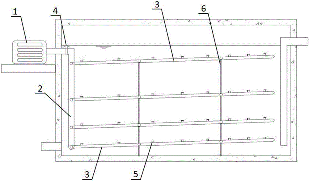
[0053] Specific embodiment 1, such as figure 1 Shown:

[0054] An optimized design of the present invention is that it is installed in a sewage treatment tank with an effective volume of 20m3, the diameter of the aeration main pipe 2 of the aeration system is 60mm, and the check valve 4 is installed. The diameter of the aeration branch pipe 3 is 10mm, and the inclination angle of 3° upwards should be taken from the horizontal when installing, and 4 layers of aeration branch pipes 3 should be installed with a distance of 150-350mm, and 5 aeration branch pipes 3 should be laid evenly on each layer. In the sewage treatment tank.

[0055] The diameter of the air aeration holes 8 on the aeration branch pipe 3 is 2-5mm. Along the air flow direction in the aeration branch pipe 3, the diameter of the aeration holes 8 gradually increases, and the spacing between the holes is 200-400mm, along the aeration branch pipe 3 The distance between the air flow directions gradually decreases. The l...

specific Embodiment 2

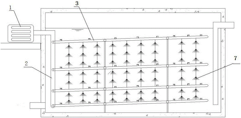
[0057] Specific embodiment 2, such as image 3 Shown:

[0058] Another optimized design of the present invention is that, installed in a sewage treatment tank with an effective volume of 50 m3, the diameter of the aeration main pipe 2 of the aeration system is set to 80 mm, and a check valve 4 is installed. The diameter of the aeration branch pipe 3 is 10mm, and the inclination angle should be 5° upward when installing. The sewage treatment tank is installed with 4 layers of aeration branch pipes 3, and the layer spacing is 150-000mm. Each layer is evenly laid with 5 aeration branch pipes 3 Distributed in the sewage treatment tank; and the aeration branch pipe 3 is used as the filler 7 support, and the filler 7 is installed on the aeration branch pipe 3.

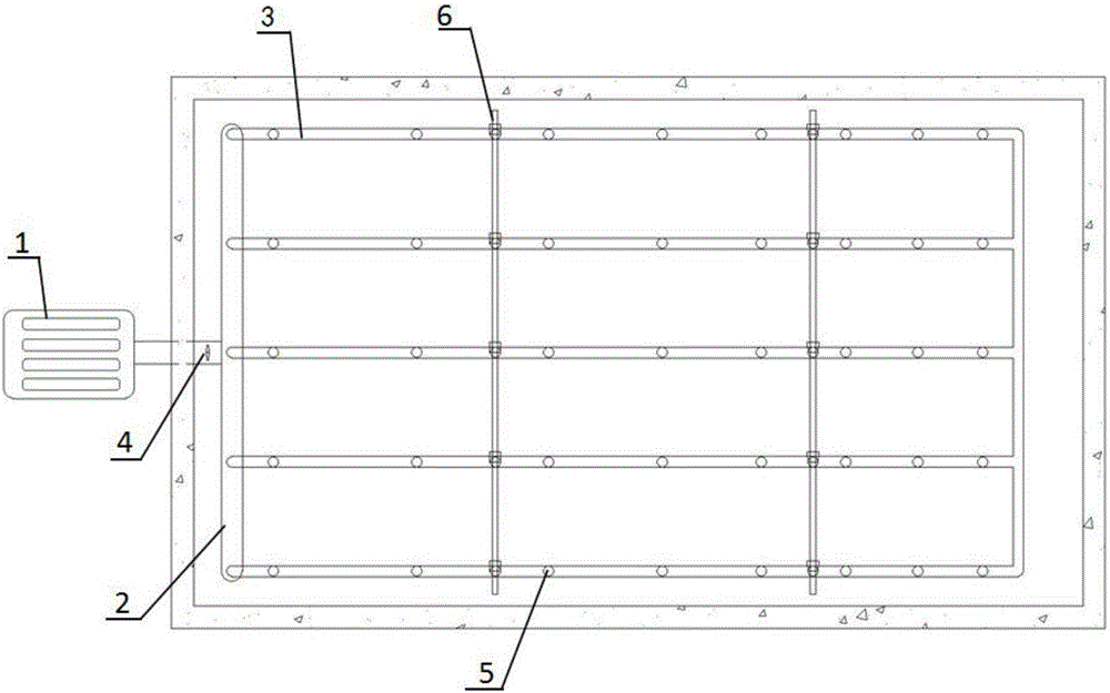
[0059] To cooperate with the realization of the method of the present invention, based on the same inventive concept, such as Image 6 As shown, the present invention also provides a micro-dynamic slow-release aeration method, i...


PUM

PropertyMeasurementUnit
pore sizeaaaaaaaaaa
thicknessaaaaaaaaaa

Abstract

The invention discloses a micropower slow-release type aeration structure and method. The aeration structure comprises an air blower, an aeration main pipe, aeration branch pipes, air shut-off discs and pipe brackets; an air outlet of the air blower is introduced into a sewage treatment pond through the aeration main pipe, the aeration main pipe is vertically arranged on one side of the sewage treatment pond, the aeration branch pipes are transversely arranged in the sewage treatment pond in a layered mode from top to bottom, the water inlet ends of the aeration branch pipes are communicated with the aeration main pipe, and the pipe brackets are perpendicular to the bottom of the sewage treatment pond and fixedly connected with the aeration branch pipes on each layer; aeration holes of different hole diameters are formed in the aeration branch pipes, and the upper ends of the aeration holes are covered with corresponding air shut-off discs. The micropower slow-release type aeration structure and method solve the problem of local oxygen insufficiency in sewage treatment, under the situation that the requirement for output water quality is unchanged, aeration time required by an aeration device is shorter, the requirement can be met just by micropower aeration, energy consumption is lowered, and operation cost of a sewage treatment device is reduced.

Description

Technical field [0001] The invention belongs to the technical field of aeration devices, and particularly relates to a micro-dynamic slow-release aeration structure and method. Background technique [0002] Energy is very scarce in our country. Therefore, the promotion of a low-carbon economy and a green economy is an important direction for my country's current development. But at the same time, my country’s environmental pollution is also very serious, especially in terms of domestic sewage treatment technology. Many rural areas and energy-scarce areas still rely on biogas digesters, septic tanks, domestic sewage purification tanks, and constructed wetlands for treatment in this regard. Unpowered sewage treatment technology. However, the limitations of these technologies are also obvious. First, the treatment efficiency is low, and the area is large. Second, the effect of nitrogen and phosphorus removal is not good, and it is difficult to meet increasingly stringent environment...

Claims


Application Information

Patent Timeline
Patent Type & Authority Applications(China)
IPC IPC(8): C02F3/02C02F7/00
CPCC02F3/02C02F7/00C02F2203/006Y02W10/10
Inventor 潘科施国中何明雄胡启春申禄坤
Owner BIOGAS SCI RES INST MIN OF AGRI
Why Eureka
Try Eureka