
A sedimentation sludge drying bed for solid-liquid wastewater treatment

A wastewater treatment and sludge drying technology, which is applied in the direction of dehydration/drying/concentrated sludge treatment, etc., can solve the problems of wasting manpower and material resources, solid-liquid sedimentation sludge is easy to form agglomerates, and takes a long time, so as to improve efficiency and shorten Working time, the effect of preventing excessive residue

Active Publication Date: 2021-08-03
扬州胜宁信息技术有限公司
View PDF4 Cites 0 Cited by
  • Summary
  • Abstract
  • Description
  • Claims
  • Application Information

AI Technical Summary

Problems solved by technology

[0005] The invention can solve the problem that the traditional solid-liquid wastewater treatment sedimentation sludge drying bed usually adopts the method of directly drying the surface, which takes a long time, and direct drying can only dry the surface of the solid-liquid sedimentation sludge, and the solid-liquid precipitation The inside of the sludge is still in a wet state, and the dried solid-liquid sedimentation sludge is easy to form agglomerates; when the traditional solid-liquid wastewater treatment sedimentation sludge drying bed uses a conveyor belt to transport the solid-liquid sedimentation sludge, due to the solid-liquid sedimentation sludge The inside of the mud is wet, and often there will be wet solid-liquid sedimentation sludge remaining on the surface of the conveyor belt, which requires manual cleaning, wasting manpower and material resources and other problems

Method used


Image

  • A sedimentation sludge drying bed for solid-liquid wastewater treatment
  • A sedimentation sludge drying bed for solid-liquid wastewater treatment
  • A sedimentation sludge drying bed for solid-liquid wastewater treatment

Examples


Embodiment Construction

[0028] The embodiments of the present invention will be described in detail below with reference to the accompanying drawings, but the present invention can be implemented in many different ways defined and covered by the claims.

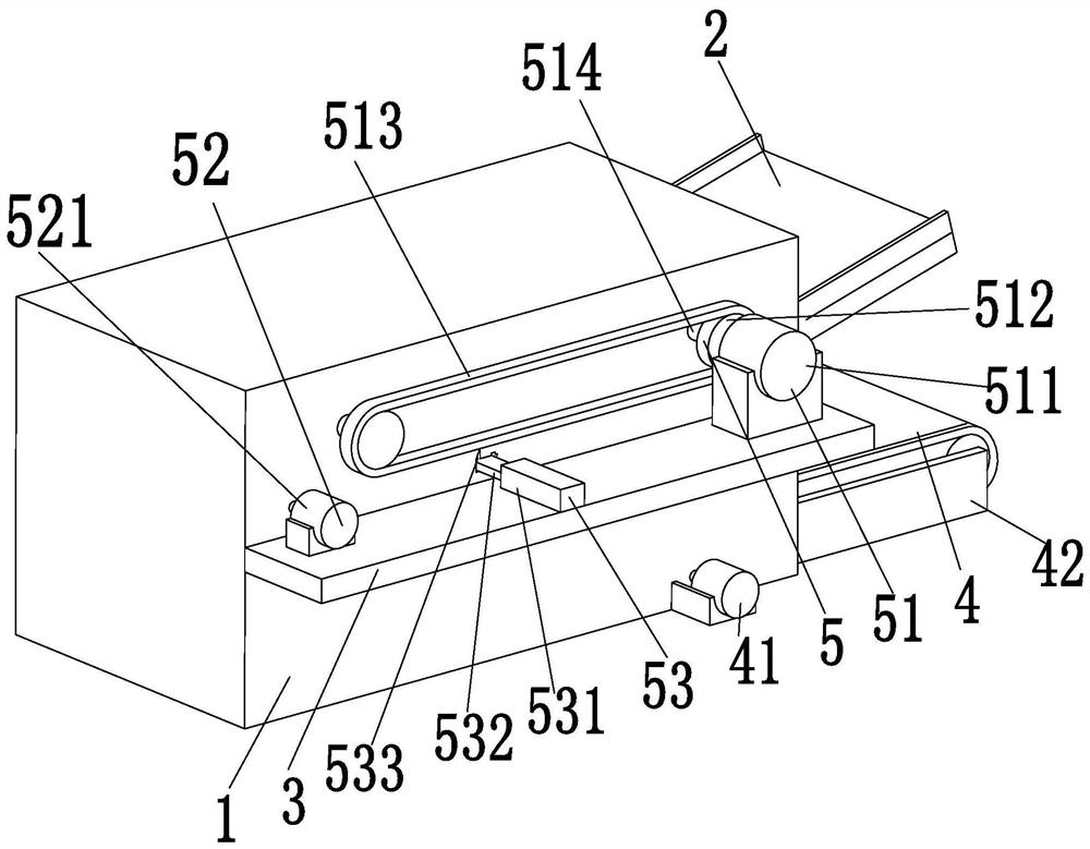
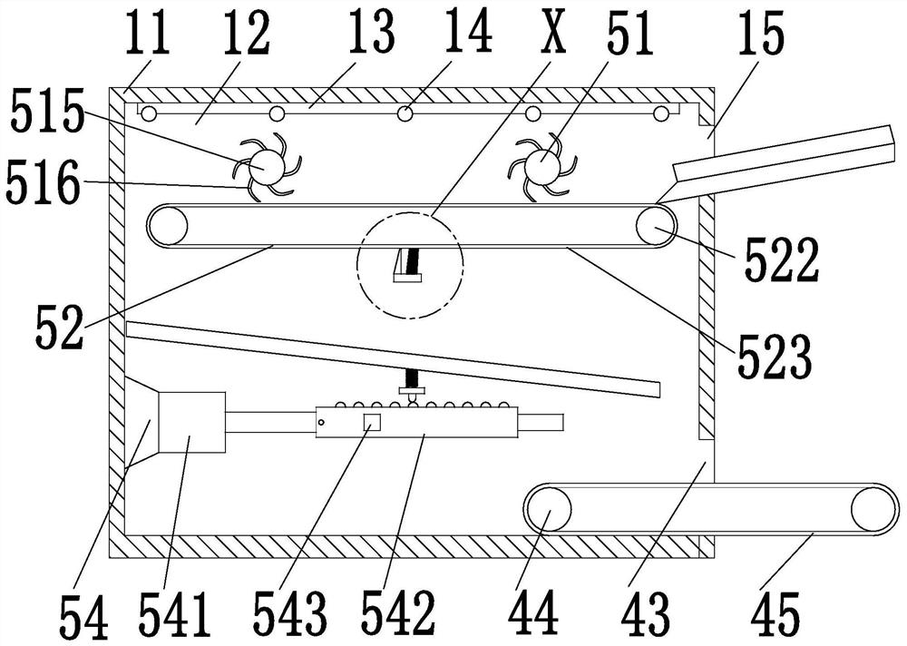
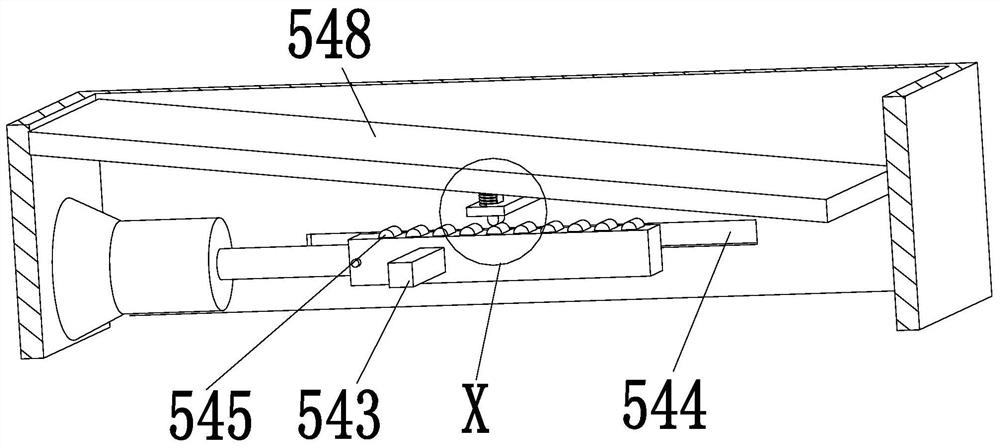
[0029] like Figure 1 to Figure 5 As shown, a solid-liquid wastewater treatment sedimentation sludge drying bed includes an installation frame 1, a feed plate 2, an installation plate 3, a discharge device 4 and a drying device 5, and the outer wall of the right end of the installation frame 1 is fixed with Feeding plate 2, installation plate 3 is installed on the outer wall of the front end middle part of installation frame 1, discharge device 4 is arranged on the inner bottom of installation frame 1, and drying device 5 is arranged on the inner top of installation frame 1.

[0030] The installation frame 1 includes an installation frame 11, a working cavity 12, a fixed plate 13, a heating rod 14 and a feed port 15, the inside of the installation f...


PUM


Abstract

The invention relates to a sedimentation sludge drying bed for solid-liquid wastewater treatment, which comprises a mounting frame, a feeding plate, a mounting plate, a discharging device and a drying device. A feeding plate is fixed on the outer wall of the right end of the mounting frame, and An installation plate is installed on the outer wall of the middle part of the front end, a discharge device is arranged under the inside of the installation frame, and a drying device is arranged above the inside of the installation frame. The invention can solve the problem that the traditional solid-liquid wastewater treatment sedimentation sludge drying bed usually adopts the method of directly drying the surface, which takes a long time, and direct drying can only dry the surface of the solid-liquid sedimentation sludge, and the solid-liquid precipitation The inside of the sludge is still in a wet state, and the dried solid-liquid sedimentation sludge is easy to form agglomerates; when the traditional solid-liquid wastewater treatment sedimentation sludge drying bed uses a conveyor belt to transport the solid-liquid sedimentation sludge, there will often be wet Solid-liquid sedimentation sludge remains on the surface of the conveyor belt, requiring manual cleaning, wasting manpower and material resources and other problems.

Description

technical field [0001] The invention relates to the technical field of solid-liquid wastewater treatment, in particular to a sedimentation sludge drying bed for solid-liquid wastewater treatment. Background technique [0002] Under normal circumstances, solid-liquid wastewater often contains a variety of pollutants. In order to obtain sedimentation sludge in solid-liquid wastewater, it is necessary to formulate corresponding plans according to the water quality, water volume, treatment degree, and possibility of recycling useful substances. Through physical The means or biochemical effects, etc., to obtain the corresponding sedimentation sludge. Sedimentary sludge is widely used. Its main characteristics are high water content, high organic matter content, easy to rot and smell, and the particles are finer, the specific gravity is smaller, and it is in a colloidal liquid state, which is a thick substance between liquid and solid. After treatment, the sludge can be used as f...

Claims


Application Information

Patent Timeline
Patent Type & Authority Patents(China)
IPC IPC(8): C02F11/13
CPCC02F11/13
Inventor 徐香庭尹荣庆
Owner 扬州胜宁信息技术有限公司
Learn More